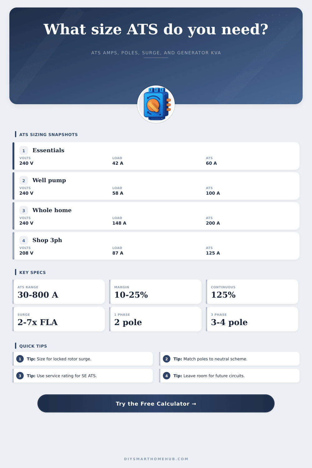
Automatic Transfer Switch Calculator
Estimate essential load amps, generator kVA fit, motor starting surge, service entrance constraint, and a practical ATS amp and pole rating.
| ATS amp frame | Typical use | 1-phase kVA at 240V | 3-phase kVA at 208V |
|---|---|---|---|
| 30 A | Small equipment branch | 7.2 kVA | 10.8 kVA |
| 60 A | Essential circuits panel | 14.4 kVA | 21.6 kVA |
| 100 A | Large critical-load panel | 24.0 kVA | 36.0 kVA |
| 150 A | Large feeder or light commercial | 36.0 kVA | 54.0 kVA |
| 200 A | Whole-home service entrance | 48.0 kVA | 72.1 kVA |
| 400 A | Large dwelling or small facility | 96.0 kVA | 144.1 kVA |
| 800 A | Commercial service entrance | 192.0 kVA | 288.2 kVA |
| Generator kW | At 0.8 PF | At 0.9 PF | 240V 1-phase amps at 0.9 PF |
|---|---|---|---|
| 10 kW | 12.5 kVA | 11.1 kVA | 46 A |
| 14 kW | 17.5 kVA | 15.6 kVA | 65 A |
| 22 kW | 27.5 kVA | 24.4 kVA | 102 A |
| 30 kW | 37.5 kVA | 33.3 kVA | 139 A |
| 48 kW | 60.0 kVA | 53.3 kVA | 222 A |
| 80 kW | 100.0 kVA | 88.9 kVA | 370 A |
| System | Formula used | Solid neutral | Switched neutral |
|---|---|---|---|
| 120/240V 1-phase | kVA = V x A / 1000 | 2 pole | 3 pole |
| 120/208V 3-phase | kVA = 1.732 x V x A / 1000 | 3 pole | 4 pole |
| 240V 3-phase | kVA = 1.732 x V x A / 1000 | 3 pole | 4 pole |
| 277/480V 3-phase | kVA = 1.732 x V x A / 1000 | 3 pole | 4 pole |
| 120V 1-phase | kVA = V x A / 1000 | 1 pole | 2 pole |
| Profile | Essential load | Motor surge | Likely ATS frame |
|---|---|---|---|
| Refrigerator, lights, boiler controls | 20-35 A | Low to moderate | 60 A |
| Well pump plus essentials | 35-65 A | High | 100 A |
| Gas home critical panel | 50-90 A | Moderate | 100-125 A |
| Heat pump subpanel | 75-130 A | High | 150-200 A |
| Whole-home service entrance | Service rating | Depends on HVAC | 200-400 A |
Sizing an automatic transfer switch is where most projects derail, but if done correctly, it keeps critical appliances operating in event of a power loss. Common mistakes include guessing on generator size or choosing an automatic transfer switch that looks large enough without calculating the actualy load it will carry. Don’t make this mistake.
Use the calculator to process your circuits data and you don’t need to guess what will trip the breaker and what won’t or how long it might take to drain the battery. One thing to keep in mind: Sizing should takes into account both continuous and intermittent loads. For example, your computer would be considered a continuous load (it’s on all day); while a blender is an intermittent load (it’s only on for a few seconds here and there).
How to Size Your Transfer Switch Correctly
According to the National Electrical Code, continuous loads is rated at one hundred twenty-five percent of their true load. If you don’t follow this guideline, the contacts in the transfer switch won’t be able to handle the constant pull. This can cause transfer switch to overheat. It’s thermal physics, something that the tool takes into account by default to ensure the hardware doesn’t burn out on a hot summer day.
Another issue are motors, which also pull large amounts of current when they start up. A typical pump, like a well pump, might draw ten amps normally but hit forty or fifty amps for a fraction of a second when it kicks on. Without sufficient capacity to supply that “spike” current, the motor will lose voltage, sputter, and stall. This requires estimating the maximum motor’s amp load plus a multiple for startup (again).
Enter the continuous amps into the calculator and select the multiple depending on whether the motor has a soft-start drive or is a direct-on-line compressor, etc. Get this wrong and guess what? Your backup power trips out just when you want it running.
The number of poles you need depends on your voltage system and whether you need to switch the neutral conductor. Typically for residential single phase services this will be 2 poles unless you have a floating neutral that requires isolation. Commercial three-phase service can has 4 poles if you want to balance conductors when transferring loads. However, switching the neutral to avoid backfeeding problems can complicate the mechanism.
The table below explains what set up lines up with your service. You don’t want to order one that doesn’t fit your panel.
How you size the generator and the transfer switch relative to each other dictates if the system will work both physically as well as financially. No one wants to have a little generator tied into a huge transfer switch because then their engine won’t be able to handle the load. And no one wants a humongous generator coupled to an undersized switch, that’s just throwing money away.
The tool considers the power factor (most residential generators is rated at a power factor of zero point eight or nine). It calculates the load in terms of kVA (kilo-volt-amperes) and compares this to size of the backup generator. If you go beyond what the kVA can support, the generator will run too hot and could shut down. So you want a match, but one with some variance to ensure the engine isn’t running at full capacity all the time.
Electrical requirements don’t diminish either, so plan ahead and have some room to expand. In the next few years, maybe you’ll add some big shop tools or a heat pump. Having a 15-20% contingency built-in today will save you from having to remodel when your critical load panel gets full. The calculator can include this reserve, which results in an amp frame recommendation that’s sufficient for todays needs but has space reserved for tomorrow’s extras.
To plan for backup power, you have to understand the physics of your equipment, not simply purchase the biggest unit possible. Sizing appropriately will keep your systems running during a storm without overloading your system or tripping it from the surge current. It’s good to take the time and get the figures correct before hooking up any wires; it gives you confidence, not confusion. You should of used calculations rather than guessing.