IEEE 1584 Arc Flash Calculator
Estimate arcing current, incident energy, and arc-flash boundary from the same field data used in an IEEE 1584-style study: bolted fault current, voltage, gap, enclosure, electrode configuration, working distance, clearing time, and arcing-current adjustment.
⚡Switchgear and MCC presets
📋IEEE 1584-style inputs
This tool uses an IEEE 1584-style approximation for screening and sensitivity checks. It is not the published IEEE 1584 equation set and must not be used as a final arc-flash label or energized-work authorization.
💡Study notes
Calculation breakdown
🔌Electrode configuration comparison grid
Vertical conductors in a box. Common baseline for LV switchgear, panelboards, and MCC compartments.
Vertical conductors terminated in an insulating barrier. Often raises calculated energy versus VCB.
Horizontal conductors in a box. Frequently severe for LV switchgear because plasma is directed outward.
Vertical conductors in open air. No enclosure focusing factor, but still requires a formal hazard analysis.
Horizontal conductors in open air. Directionality can increase exposure compared with vertical open air.
📊Reference tables
| IEEE 1584-style input | Common study value | Why it matters | Check before use |
|---|---|---|---|
| System voltage | 208 V to 15 kV AC | Affects arcing-current behavior and applicable model range | Use nominal equipment voltage at the bus |
| Bolted fault current | Site short-circuit kA | Starting point for arcing current and device trip time | Use available current from a current study |
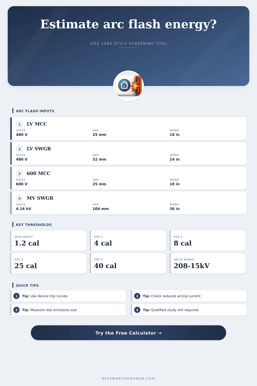
| Electrode gap | 25 mm LV MCC, 32 mm LV gear, 104 mm MV gear | Changes arc voltage, current, and energy transfer | Measure actual phase spacing where possible |
| Working distance | 18 in MCC, 24 in LV gear, 36 in MV gear | Incident energy falls with distance from the arc source | Use task-specific face and torso distance |
| Equipment class | Typical voltage | Typical gap | Typical working distance |
|---|---|---|---|
| MCC bucket or starter section | 208-600 V | 25 mm | 18 in / 455 mm |
| Low-voltage switchboard | 208-600 V | 25-32 mm | 18-24 in / 455-610 mm |
| Low-voltage drawout switchgear | 480-600 V | 32 mm | 24 in / 610 mm |
| Medium-voltage metal-clad switchgear | 2.4-15 kV | 104-152 mm | 36 in / 915 mm |
| Incident energy level | Common threshold | Typical meaning | Use limitation |
|---|---|---|---|
| Arc-flash boundary basis | 1.2 cal/cm² | Common onset of second-degree burn threshold | Boundary may be solved for another target |
| Arc-rated clothing category 1 | 4 cal/cm² | Minimum arc rating for category 1 systems | Do not mix table method and study method |
| Arc-rated clothing category 2 | 8 cal/cm² | Common daily arc-rated clothing threshold | Use employer PPE program requirements |
| High-energy range | 25-40 cal/cm² | Category 3 and 4 comparison levels | Requires careful task and equipment review |
| Configuration | Approx. energy tendency | Typical location | Screening note |
|---|---|---|---|
| VCB | Baseline | Panelboards, MCCs, LV switchgear | Often default when conductors are vertical in box |
| VCBB | Higher than VCB | Terminations facing an insulating barrier | Barrier can focus energy toward worker |
| HCB | Often highest enclosed LV case | Drawout gear and bus compartments | Horizontal conductors can project plasma outward |
| VOA / HOA | Lower enclosure effect | Open-air conductors and outdoor structures | Still depends on task, geometry, and distance |
An arc flash occur when energy is sudden released within the energized equipment, and the resulting arc flash can create burn hazard within milliseconds of the incident. Because an arc flash is such a serious hazard, many facility will perform arc flash studies to determine the degree of that hazard. As a result, many facilities employ tools based on the IEEE 1584 model that allow them to quickly perform arc flash checks in the equipment they operate.
The calculator included in this article will allow you to quickly perform arc flash checks for your facility. Bolted fault current is the available short-circuit current that can exit the terminal of the equipment. The current that arc between the equipment is always less than the bolted fault current, as the arc itself add resistance to the electrical circuit.
How to Use a Quick Arc Flash Calculator
However, the arcing current may cause the protective device of the equipment to take longer to clear the fault. As such, the adjustment field allow you to test the effect of the difference between the bolted fault current and the arcing current, a parameter that is difficultly to determine without formal arc flash studies. Voltage play a role in the arc flash because the physics of the arc flash are different at different voltage level.
As such, the IEEE 1584 model use different factors to calculate the energy of the arc flash at different voltage levels. For instance, arc flash are less stable at voltages under 300 volts. At higher voltages, more energy is directed into the arc flash.
Thus, the calculator account for voltage differences when calculating arc energy, such as between 480-volt motor control center and 4-kilovolt switchgear. Electrode configuration is another variable in arc energy; the way in which the conductor are arranged will affect the energy of the arc flash. For instance, vertical conductor within a box will behave differently than horizontal conductors within the same box.
Additionally, placing a barrier at the arc flash will alter the energy of the arc flash. These factor can be adjusted within the calculator to provide engineers with a view into how the energy of the arc flash will change due to these variables. The dimension of the enclosure in which the electrical equipment is installed will impact the energy of the arc flash.
Arc energy will be directed outward from a shallow and narrow enclosure, while some of the energy will dissipate before reaching the enclosure if the enclosure is deeper than narrow enclosure. These dimensions can be entered into the calculator to determine the impact that a deeper enclosure may have on arc energy. Working distance is another variable that engineers can be control, and is one of the most effective in reducing the risk of arc flash injury.
Moving an individual even six inch away from electrical equipment can significantly reduce the energy of the arc flash that reaches the human being. The reference table can provide engineers with the working distances for various type of electrical equipment, but the calculator can be used for any specific working distance for a task. Clearing time is the amount of time that a protective device take to clear a fault.
For example, if a relay take 80 milliseconds to clear a fault rather than the 200 milliseconds it would normally take, the energy of the arc flash will be almost half of the energy that would occur at that longer time. Because clearing time is one of the most critical parameter for electrical protection devices, most formal arc flash studies focus upon verifying trip curves for those device. Thus, the adjustment field within the calculator can be used to test different clearing time for the same equipment.
When you enter the parameters for your specific facility into the calculator, you will be able to determine the adjusted arcing current, the incident energy at the working distance, and the distance of the arc flash boundary. Each of these parameter will only provide engineers with a screening value to determine if the current fuses, working position, or enclosures of the electrical equipment will move the incident energy to a lower category of personal protection equipment (PPE) requirements. Thus, these screening value will help engineers determine whether the performance of a formal arc flash study is necessary at all locations.
The value of this quick arc flash calculation tool is that it ask engineers to gather important data about their facilities. For instance, a short circuit study of the power supply must determine the actual bolted fault current at each location. Additionally, the gap between the electrode at the equipment will need to be measured, as will the clearing time of the electrical device that supply that equipment.
These effort will uncover any gap in the documentation of electrical equipment within the engineers’ facilities. Finally, while this quick calculation tool is helpful for engineers in estimating the arc flash energy at different variables, it is not a replacement for the formal arc flash studies that must be completed at facilities with energy level near the thresholds for personal protection equipment (PPE). Instead, such an estimation tool can help engineers recognize when they should of hire a qualified engineer to complete a formal arc flash study that uses the complete IEEE 1584 equation and verified electrical device curve and drawings.