AIC Fault Current Calculator
Estimate available fault current at a panel, compare it with breaker AIC rating, and see how transformer impedance, conductor impedance, series ratings, and safety margin affect the pass or fail status.
Panel and Breaker AIC Presets
Choose a starting point, then adjust the transformer, feeder, and breaker values for the actual equipment label and utility data.
Fault Current Inputs
AIC Results
Calculation Breakdown
Selected Breaker and Feeder Spec Grid
Breaker AIC Spec Grid
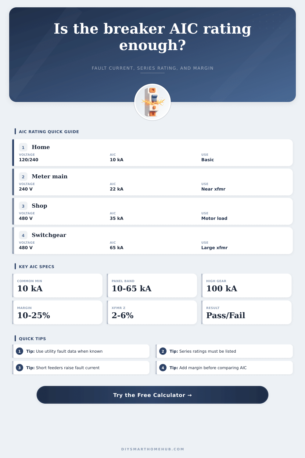
| AIC rating | Typical equipment | Common voltage class | Use in calculator |
|---|---|---|---|
| 10 kAIC | Residential branch breaker | 120/240 V | Small service or longer feeder |
| 14-18 kAIC | Load center or bolt-on branch | 120/240 V, 208 V | Moderate available fault current |
| 22-25 kAIC | Service panel or panelboard | 208 V, 240 V, 480 V | Nearer transformer installations |
| 35-42 kAIC | Commercial molded case gear | 208 V, 480 V | Short feeder, larger transformer |
| 65-100 kAIC | Switchboard or power breaker | 480 V, 600 V | Large service gear |
| 200 kAIC | Current-limiting listed gear | Low voltage systems | High fault duty with listed devices |
Transformer Fault Current Reference
| Transformer | Voltage | Impedance | Approx source kA |
|---|---|---|---|
| 25 kVA single phase | 120/240 V | 2.0% | 5.2 kA |
| 50 kVA single phase | 120/240 V | 2.5% | 8.3 kA |
| 75 kVA three phase | 208 V | 3.0% | 6.9 kA |
| 112.5 kVA three phase | 480 V | 3.5% | 3.9 kA |
| 500 kVA three phase | 480 V | 5.75% | 10.5 kA |
| 1000 kVA three phase | 480 V | 5.75% | 20.9 kA |
Conductor Reduction Reference
| Feeder condition | Fault current effect | Calculator input | Planning note |
|---|---|---|---|
| Service gear at transformer | Minimal reduction | 0-10 ft | Breaker AIC often highest here |
| Short panel feeder | Small reduction | 10-50 ft | Use actual conductor size |
| Remote subpanel | Moderate reduction | 75-200 ft | Long run can lower required AIC |
| Parallel feeders | Less impedance | 2+ sets | Fault current may rise sharply |
| Aluminum feeder | More resistance | Al size | Compare by actual ohms, not ampacity |
Common Project Size Checks
| Project | Typical source | Likely AIC band | Secondary check |
|---|---|---|---|
| Detached home load center | 25-50 kVA single phase | 10-22 kAIC | Utility fault at meter |
| Small apartment panel | 75-150 kVA bank | 14-25 kAIC | Meter stack series label |
| Garage or studio subpanel | Long feeder | 10-18 kAIC | Conductor length reduction |
| Commercial lighting panel | 112.5-225 kVA | 22-42 kAIC | 480 V transformer impedance |
| Motor control center | 300-1000 kVA | 42-65 kAIC | Motor contribution percent |
| Main switchboard | 750-2500 kVA | 65-100 kAIC | Utility and X/R data |
AIC Calculation Tips
To protect devices you must figure out how much fault current is available and whether it will kill your equipment when there is a short circuit. If it will cause more than what the device is rated for then it doesn’t trip normally. It explodes. To find out if that happens you look at the Ampere Interrupting Capacity (AIC). The label on your breaker show the max energy it will stop. Why? Its interrupting capacity is what keeps you safe.
If you know the impedance and transformer size, the calculator will do math for you. It saves some time on conversions. So what’s the next thing to figure out? What size transformer are we talking about? In residential work, it might be a modest 25kVA pad-mounted unit down the street. At a commercial building it may be a huge 500kVA located somewhere around switchgear.
How to Calculate Fault Current for Safety
Knowing the kva of the transformer is key to how much energy can flow through. For instance, a big old 500 kva transformer have a bigger core with less resistance inside. This means that when a fault occur, there is going to be significantly more current coming out the other side. That’s why starting with the transformer size help us get an idea of the risk level at your panel.
It also takes into account impedance. When a short occurs in a circuit, impedance is the measure of how that transformer resists the current flow (expressed as a percentage). The lower the impedance, the higher the fault current. That’s why a transformer rated with only two percent impedance will pass more current then one rated with six percent. And that’s what the calculator determines, the highest level of surge until wires cut it back. If you’re working around service entrance, this raw number is your starting point.
But then there are the conductors. Each one has resistance. It’s their version of speed bumps for electrons. Longer feeder runs use up some of the available fault current at distant panel. How much? Again, material selection impacts that. Copper conducts better than aluminum. An equal-length aluminum feeder will thus drop more voltage (and restrict fault current) than a copper feeder. The table below show the effect that various scenarios have on final figure.
This gets even more complicated with motor loads. When power fails or shorts, large rotating motors don’t immediately stop. They continue to spin for several cycles because of their inertia. That causes them to become temporary generators, feeding current back into the fault. It is very little compared to the power from the utility. However, it is enough to tip the calculation in the other direction on a borderline case. Designing to worst case includes these margins.
When you’re dealing with series ratings, meaning the downstream breaker is rated for less current than what comes into it… You get around that problem by having a higher current on the upstream breaker or fuse and the downstream one. When both devices is listed as a combination (upstream + downstream), they will trip at the lower value, even though individually they might not be able to handle it. This holds true for these two devices. Changing out either part mean the whole thing is no longer listed. And, yes, that means the safety guarantee goes away. Why? Because the devices were tested together. But you should of follow the strict documentation.
Lastly, use a safety margin. Add 15% to whatever figure you arrive at to give yourself some breathing room in case you missed something or need to upgrade the electric later. We’re not passing code; we’re trying for reliable service over the long haul. Running a breaker up to (and sometimes beyond) its rating mean you are flirting with danger. You want it running well below its interrupting capability. You don’t want it scraping by barely surviving a fault.
Calculating out what you’ve got is how to do electrical safety. That’s not guesswork. Knowing the number means there is no more doubt. Competence.