Star Delta Contactor Sizing Calculator
Estimate three-phase motor full-load current, main contactor current, delta contactor current, star contactor current, overload setting, transition timer, and starting current reduction for star-delta starter planning.
⚡Star-delta motor presets
📋Motor and starter inputs
Use the motor nameplate when available. Star-delta starters are normally used on motors built for delta running at the selected line voltage, with six motor leads brought to the starter.
Star-delta sizing result
Calculated motor FLA and contactor currents will appear here.
🔧Contactor and timer spec grid
📐Star-delta formulas used
| Item | Formula | What it means | Common sizing use |
|---|---|---|---|
| Motor FLA | W output / (sqrt(3) x V x PF x efficiency) | Estimated running line current from nameplate data | Base current for the starter worksheet |
| Main contactor | FLA x margin factor | The line contactor carries motor line current in run | Choose next AC-3 rating at selected voltage |
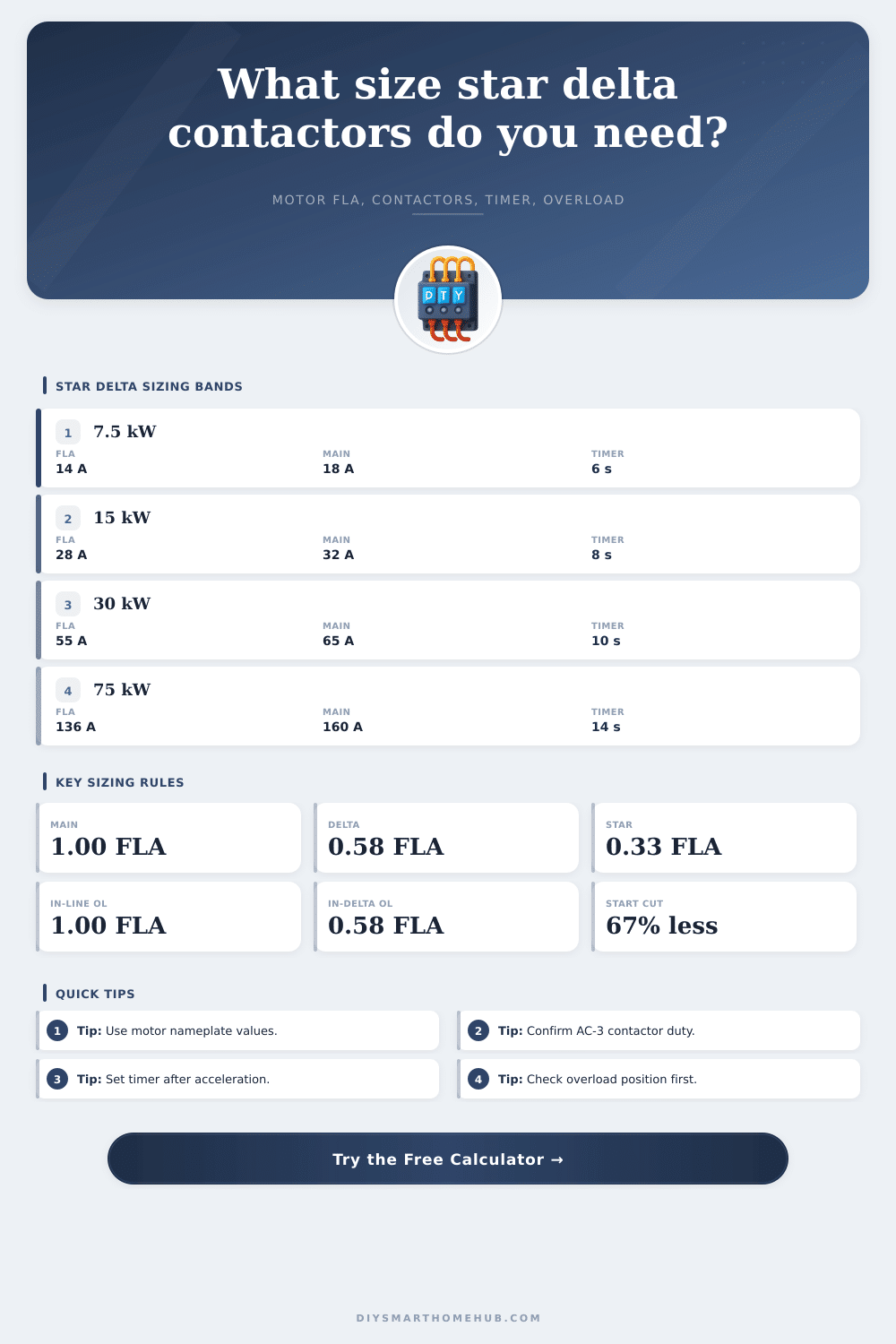
| Delta contactor | FLA / sqrt(3) | Delta contactor carries winding phase current | About 58% of line FLA before margins |
| Star contactor | FLA / 3 | Star contactor carries reduced phase current during start | About 33% of line FLA before margins |
| Starting current | DOL start current / 3 | Star connection reduces line starting current to one third | Rough 67% reduction compared with DOL |
🔌Contactor current reference
| Motor line FLA | Main contactor | Delta contactor | Star contactor |
|---|---|---|---|
| 10 A | 10 A base, next AC-3 size with margin | 5.8 A base winding current | 3.3 A base starting contactor current |
| 25 A | 25 A base, often 32 A with margin | 14.4 A base winding current | 8.3 A base starting contactor current |
| 50 A | 50 A base, often 65 A with margin | 28.9 A base winding current | 16.7 A base starting contactor current |
| 100 A | 100 A base, often 115 A with margin | 57.7 A base winding current | 33.3 A base starting contactor current |
⏱Timer and transition reference
| Load type | Typical star time | Transfer target | Timer check |
|---|---|---|---|
| Centrifugal pump | 4 to 8 seconds | Near stable acceleration current | Short enough to avoid stalled heating |
| Compressor | 6 to 10 seconds | Motor mostly accelerated | Confirm unloaded start condition |
| Fan or blower | 8 to 18 seconds | High speed before delta close | Watch long acceleration thermal limit |
| Conveyor or machine | 5 to 12 seconds | Smooth transfer without drop-out | Validate under loaded start conditions |
🛡Overload relay position table
| Overload location | Setting formula | Current measured | Planning note |
|---|---|---|---|
| In line with supply | FLA x setting factor | Motor line current | Most familiar setting method for many panels |
| Inside delta circuit | FLA / sqrt(3) x setting factor | Winding phase current | Common in compact star-delta assemblies |
| Electronic overload | Use device manual and CT location | Depends on sensor placement | Check whether the relay expects line or phase current |
| Thermal overload | Use motor nameplate FLA basis | Heat model of selected relay | Ambient and enclosure conditions can affect selection |
📊Preset motor worksheet table
| Preset | Voltage | Expected FLA band | Starter sizing focus |
|---|---|---|---|
| 7.5 kW pump | 400 V | 13 to 16 A | Basic starter and short star time |
| 15 kW compressor | 400 V | 27 to 31 A | Main contactor and overload check |
| 30 kW blower | 415 V | 52 to 60 A | Timer and high-inertia transfer |
| 75 kW process pump | 400 V | 130 to 145 A | Contactor margin and panel ambient |
| 100 hp motor | 480 V | 115 to 130 A | hp input with NEMA-style voltage |
💡Calculation tips
Electrical safety note: This calculator is a planning worksheet. Final contactors, overloads, short-circuit protection, conductor sizes, interlocks, utilization category, coordination type, and code compliance must be verified from manufacturer data and by a qualified electrical professional.
Now that’s where working with a star delta starter panel presents its own problem, it has three contactors, one timer and one motor nameplate. If you’ve worked with one before, wiring is simple enough but it’s easy to get tripped up in sizing. You might size everything correctly to handle the full load current but size components for winding current, thus damaging main contactor on first start. It’s an engineer mistake as they thinks all three contactors are designed for the same amperage. Not true. The calculator above use your motor data to help you avoid this costly mistak.
So what’s the big idea with star delta? Well, reduce the voltage. When you crank up a big old induction motor directly on line, it pulls six to seven times rated current. This stresses mechanical couplings, dims lights and trips circuit breakers. By connecting the windings in star, you reduce the voltage on each winding by the square root of three, meaning the starting current decreases about two thirds.
How to Size Star Delta Starter Parts
It is a simple solution and good enough for many applications but there is a downside: you lose torque. Because torque is proportional to voltage squared, you’ll recieve only one third the starting torque. It is not a great way to try to start something like a conveyor belt carrying heavy load from a standstill. Compressors, pumps, and fans starts easily, running light then slowly ramping up, star delta is the ticket for these device.
To properly rate the contactors you need to know direction of flow. When running, current from the motor travels through the delta contactor connecting just two corner points of triangle. In a well-balanced three-phase system, the current through each leg of the delta winding are reduced by the square root of three compared to line current. Therefore, a delta contactor should of been rated at approximately 58 percent of the motor’s full load current. Because the star contactor only “sees” current for very short time when starting, it gets an even smaller rating; about one third of the full load current. Out of habit, engineers frequently oversize this equipment which wastes both money and precious panel space.
Balancing physics and intuition, you set the timer. You cannot switch to delta immediately, or motor will stall because it has not built up enough speed, but if you wait too long then you’ll run it at low torque and windings will get too hot. The calculator find this period for you given the load type and its inertia. If it’s a big industrial fan with lots of inertia, it may take ten or even fifteen seconds to spin up to point where the transfer shock won’t damage drive train. If it’s a centrifugal pump, which spins up quickly, you only give it brief start time (say four to six seconds).
Another item that trips folks up is where the overload relay is located. When positioned on line, set the overload at full load amps for motor. When the relay is within the delta circuit (common with compact starters), set the overload for the smaller current winding. This factor of root three can cause the overload protection to fail or trip nuisance faults and is something not to be forgotten. Always verify whether the overload is on the motor side or contactor side before adjusting setting.
Sizing is a matter of honoring the direction of flow rather than complicated math. The full load goes to main. The winding share goes to delta contactor, while star contactor performs momentarily and then gives way. Visualize it as three separate circuits with their own electrical demands, and sizing tables appear logical more than strange. Yes you should always check surrounding temps and thermal limitations for packed panels but for all practical applications, the proportional relationships remains the same. Respect the math, set timers conservatively, and position overloads based off direction of current.