3-Phase Fault Current Calculator
Estimate three-phase bolted fault current from transformer kVA, secondary voltage, percent impedance, X/R ratio, feeder impedance, motor contribution, source stiffness, and switchgear rating.
📌Three-phase system presets
⚙Fault current inputs
Use line-to-line voltage for the three-phase voltage input. Feeder R and X are entered per 1,000 ft per phase; the calculator scales them by length and parallel runs.
Fault current result
Calculated three-phase RMS fault current and momentary peak.
🔌Transformer and switchgear grid
📊Preset fault current reference
| Scenario | Typical voltage | Transformer profile | Planning signal |
|---|---|---|---|
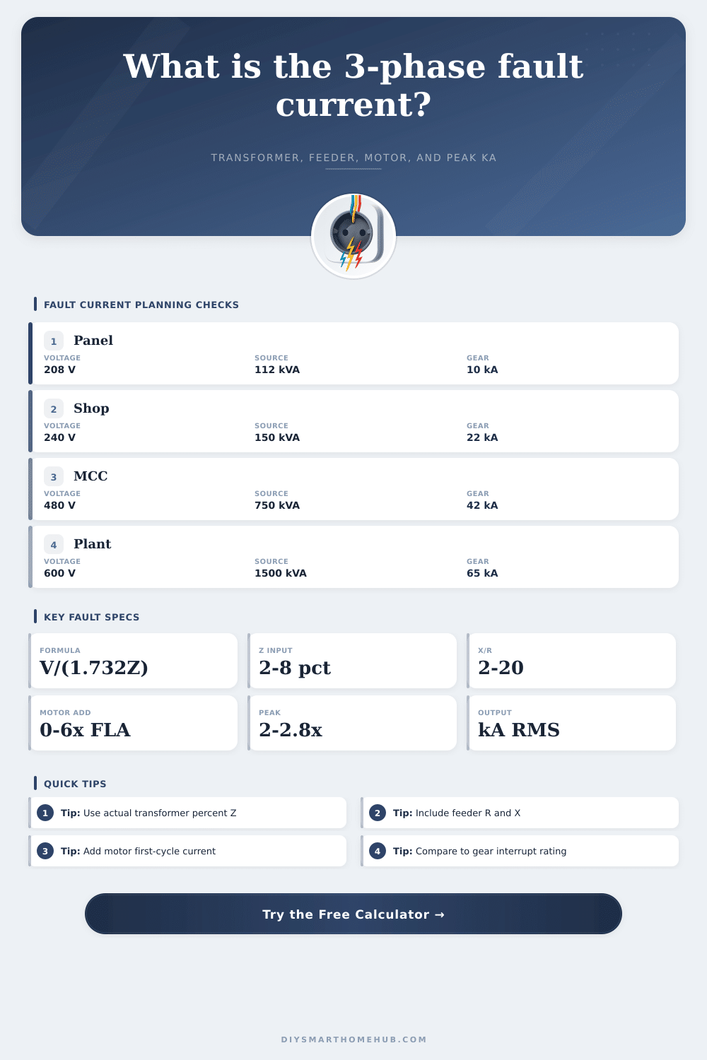
| Apartment distribution | 208 V three phase | 112.5 to 300 kVA, 3.5% to 5.0% Z | Often below 22 kA after feeder impedance |
| Commercial main panel | 480 V three phase | 300 to 750 kVA, 5.0% to 5.75% Z | Frequently in 18 to 42 kA gear range |
| Motor control center | 480 or 600 V | 750 to 1500 kVA plus motor contribution | Check first-cycle RMS and peak duty |
| Plant switchgear | 480 or 600 V | 1500 kVA and larger, high X/R | Interrupting and close-latch ratings both matter |
🧮Transformer impedance table
| Transformer type | Common percent Z | X/R planning range | Fault-current effect |
|---|---|---|---|
| Small dry-type transformer | 2.0% to 4.5% | 2 to 5 | Can produce high kA relative to its kVA |
| General low-voltage dry-type | 4.5% to 5.75% | 4 to 8 | Typical commercial panelboard source |
| Pad-mounted utility transformer | 5.0% to 6.5% | 6 to 12 | Primary source stiffness changes final kA |
| Large substation transformer | 5.5% to 8.0% | 10 to 25 | May have high close-latch peak duty |
📏Feeder impedance examples
| Feeder example | Approx R ohm/1000 ft | Approx X ohm/1000 ft | Calculator use |
|---|---|---|---|
| Large copper in steel raceway | 0.025 to 0.050 | 0.030 to 0.050 | Use for short high-capacity switchgear feeders |
| Medium copper branch feeder | 0.060 to 0.120 | 0.035 to 0.060 | Often meaningful beyond 100 ft |
| Aluminum service conductors | 0.040 to 0.100 | 0.030 to 0.055 | Check conductor and raceway-specific data |
| Parallel feeder sets | Entered value divided by runs | Entered value divided by runs | Parallel paths raise available downstream kA |
🛡Switchgear duty checkpoints
| Equipment duty | Compare calculator output | Typical label | Watch item |
|---|---|---|---|
| Interrupting rating | Symmetrical RMS fault kA | 10, 22, 42, 65, 100 kA | Motor contribution can push near limits |
| Momentary or close-latch | Asymmetrical peak kA | Peak or momentary current rating | High X/R raises first-cycle duty |
| Series rating | Available kA at load equipment | Panel and breaker series combination | Only valid for listed combinations |
| Current-limiting device | Let-through from manufacturer data | Fuse or breaker let-through curve | This calculator does not model let-through |
💡Calculation tips
So what does all this mean? Plug-in some information about your system (above) and calculator do the rest, no more wrangling with strange impedance triangles by hand.
Start with the fundamentals of transformer size and voltage. Percent impedance, though, that’s the good stuff. Think of it as resistance inside the transformer to chaos. The smaller the percent, the less opposition there is to fault current. So if you’ve got a tiny dry-type transformer rated for only two percent impedance, it’s going to allow an immense amount of current to flow before those breakers even begin to blink. And don’t guess here; use nameplate info. Two and three percent Z may not seem like much on paper, but in terms of amps at the panelboard, we’re talking tens of thousands.
How Fault Current Works
The other thing is distance. I can’t tell you how many times we thinks that the fault current at the switchgear equals the fault current ten feet from there. It doesn’t. Feeder impedance behaves like a brake. With a smaller conductor and longer run, less current will flow and voltage drop will be greater under short circuit conditions. Those cables will have both resistive and reactive component that need to be accounted for. And then there’s that little thing about parallel runs changing the game completely. Run two sets of conductors rather than one big fat set and you’ll cut the impedance maybe in half. That means double potential fault duty downstream. It is a small thing, but it matters when choosing your breakers.
Many engineer get burned by motors. Motors don’t just draw power. They generate it. When a fault happens nearby, all those induction motor on that bus become a temporary generator. They spin down into the fault, adding significant current to the mix, which can sometimes double original stress on the breakers. You need to figure out whether or not you want to include this contribution. If you’ve got hundreds of horsepower motors on a large plant setup, not considering this factor is recipe for blown equipment. The tool allows you to adjust this multiplier based off your motor load profile.
Lastly, compare the outcome to your switchgear rating. How much RMS current (symmetrical) can this thing chop-off without ruining itself? That is called interrupting rating. What about the peak (asymmetrical) surge in the very first cycle? That’s momentary duty. They are two different animals. Your breaker may be rated for the thermal load, yet fail mechanically from magnetic force of a high X/R ratio spike. Don’t cut it close; always leave some margin.
There is also some helpful benchmark tables on the page that can serve as a sanity check when plugging in normal situations (UPS boards at data centers, office mains) to see if your numbers makes sense. If they’re dramatically off the norm in the table, go back and check your feeder length and source stiffness. Typing a decimal point one place off is easy to do.
Respect the unseen, that’s what electrical safety is all about. Fault current is not something you can see, but you CAN know how much of an impact it could have. You understand how far away it is, how much resistance there is and how much it will contribute through each motor, and make these fearsome abstractions into numbers you can manage. Spend some time making sure your equipment are rated for the worst case. Overspecifying your breaker is better than cleaning up after an arc flash. Keep it simple, keep the system as stable as possible when it tends to become unstable.