Arc Flash Label Calculator
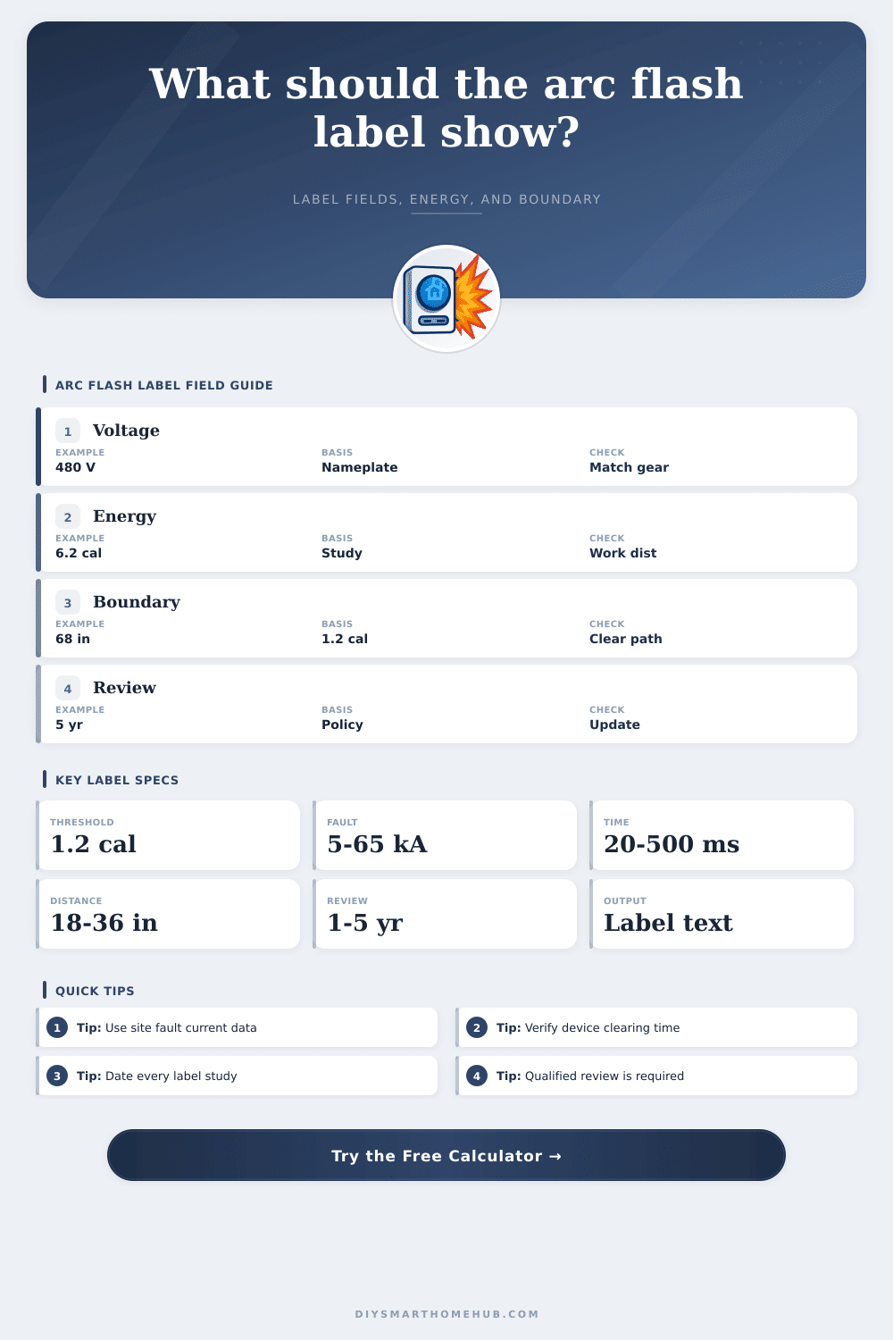
Estimate the fields that appear on an arc flash equipment label: nominal voltage, incident energy, arc flash boundary, working distance, available fault current, clearing time, PPE level, and review date.
📌Label Scenario Presets
⚙Equipment And Study Inputs
📊Label Results
🏷Draft Label Text And Breakdown
🧾Label Field Spec Grid
📘Reference Tables
| Equipment class | Default gap | Default distance | Label note |
|---|---|---|---|
| Panelboard or load center | 25 mm | 18 in / 45.7 cm | Often compact, short working distance |
| Motor control center | 32 mm | 18 in / 45.7 cm | Bucket and starter compartments vary |
| Switchboard | 45 mm | 24 in / 61.0 cm | Main and feeder sections may differ |
| Low-voltage switchgear | 45 mm | 24 in / 61.0 cm | Use exact cubicle and device data |
| Medium-voltage switchgear | 104 mm | 36 in / 91.4 cm | Requires specialist system study |
| Incident energy result | Label PPE level | Minimum arc rating text | Label action wording |
|---|---|---|---|
| Less than or equal to 1.2 cal/cm2 | Below threshold | Task and shock PPE still apply | Qualified review before energized work |
| More than 1.2 to 4 cal/cm2 | PPE 1 | Minimum 4 cal/cm2 | Arc-rated PPE required inside boundary |
| More than 4 to 8 cal/cm2 | PPE 2 | Minimum 8 cal/cm2 | Use site-specific energized work controls |
| More than 8 to 25 cal/cm2 | PPE 3 | Minimum 25 cal/cm2 | Detailed job planning required |
| More than 25 to 40 cal/cm2 | PPE 4 | Minimum 40 cal/cm2 | High energy, avoid energized work if possible |
| More than 40 cal/cm2 | Danger | Above common PPE table range | Do not use this draft without engineering review |
| Label field | What to enter | Source to verify | Common mismatch |
|---|---|---|---|
| Nominal voltage | System voltage, not test voltage | One-line, nameplate, study | Using utilization voltage only |
| Available fault current | Bolted fault current at equipment | Utility data and feeder model | Using transformer secondary only |
| Clearing time | Total protective device clearing time | TCC curve at arcing current | Using bolted fault trip point |
| Working distance | Distance used for incident energy | Equipment class and task posture | Copying a generic 18 inch value |
| Review interval | Company policy or code-driven cycle | Safety program and change log | Ignoring system modifications |
| Scenario | Typical voltage | Fault current range | Review trigger |
|---|---|---|---|
| Office distribution panel | 208 to 480 V | 5 to 25 kA | Tenant or feeder change |
| Motor control center | 480 to 600 V | 15 to 50 kA | Fuse, breaker, or motor additions |
| Main switchboard | 480 to 600 V | 25 to 65 kA | Utility transformer change |
| UPS or inverter cabinet | 208 to 480 V | 5 to 35 kA | Bypass or battery system change |
| Medium-voltage gear | 4.16 to 13.2 kV | 8 to 40 kA | Relay setting or utility change |
💡Practical Tips
An arc flash happens in milliseconds, which isn’t enough time to react. Once electricity jumps across air rather than the copper, it transform the atmosphere into a superheated plasma, as hot as surface of sun. Before we see anything, it has already changed.
In that split second, arc flash labeling must guide us with no room for misunderstanding. When faults happen, you can’t prevent physics from acting, but you can direct workers precisely where they should be standing and which protective equipment they should use. By translating raw electrical data into usable safety information, the calculator on this page allow you to write those instructions.
Why Arc Flash Labels Are Important for Safety
Too many facilities view them as static stickers, like those used for inspections years ago. No, they’re living documents connected to current electrical condition of your facility. Adding a solar array? Modifying a breaker setting? Changing out a transformer? Any change in the system means that current label might be inaccurate. Change the system, move the boundary and change level of energy present.
When the system do change, a qualified review is needed. Otherwise, the out-of-date label gives you a false sense of security. It implies safety when, in fact, there’s a death zone.
But there’s one place folks tend to trip up: accurate inputs. Because, as mentioned earlier, voltage isn’t everything. Voltage alone doesn’t determines danger. Incident energy is created by two things: available fault current and clearing time. Available fault current is the amount of power that can feeds the arc. Clearing time is how quickly protection devices shut that power down.
You could have high fault current and fast clearing, or you could have low fault current and slow clearing, it would be better to have the first option. Why? Because the longer the arc, the longer it has to release energy into the space. When you put those two factors into the calculator (and all its other variables), it will do the math for you and spare you any hand-calculating errors you might make via a spreadsheet.
Distance also makes a difference. The electrical worker in a tight motor control center working on a breaker is closer to energy source compared to another person standing behind him at a huge switchboard. Because of this close proximity, their exposure to the heat become much more intense. Eighteen or twenty-four inches are typical for assumed distances and even though it’s a default number, it needs to align with the physical constraints of the job and the equipment. Using an assumed distance that doesn’t apply to your work because you have to reach further into enclosure will result in improper PPE calculations.
The table on the page show what default distances and gaps applies to various pieces of equipment based off class so you can eliminate generic guesses that don’t reflect your reality. The output provides two important bits of data. The first is the incident energy level (calories per square centimeter), which determines what type of personal protective equipment will be necessary.
The second is the arc flash boundary, which is the area surrounding the equipment where there’s enough energy to cause an arc flash but not enough to cause second degree burns (typically at 1.2 calories). If anyone moves into the boundary they should of had appropriate arc-rated clothing on. Beyond it they’re generally safe from second-degree burns caused by the flash. Not having enough protection or using too much expensive gear depends upon actualy calculating the distance.
The review date field is not administrative fluff; many facilities neglect to use it. Over time, the electrical system degrade and evolves. Settings drift and protective devices age. Typically, there’s a five-year review schedule. But any significant change warrant an instant update. While you’re working on today’s electrical system, you don’t want to read a label based off what was in place decades ago.
Clarity is the name of the game. An electrician entering a panel should instantly see the boundary, the hazard level, and the voltage clearly labeled. They shouldn’t need to page through binders or dial an engineer to determine whether their clothing might provide protection. Removing guesswork from hazardous environments save lives.
Update the labels whenever the system changes; double-check your data sources; treat them with respect. The silence prior to the arc is short. The preparation should last forever.