Arc Flash Boundary Distance Calculator
Estimate incident energy at working distance, arcing current, clearing-time effect, and the distance where energy falls to the 1.2 cal/cm2 arc flash boundary threshold.
⚡Equipment presets
📏Arc flash inputs
Arc Flash Boundary Results
🧰Equipment and electrode spec grid
📋Equipment preset reference table
| Preset | Voltage | Fault current | Clearing time | Working distance | Starting assumption |
|---|---|---|---|---|---|
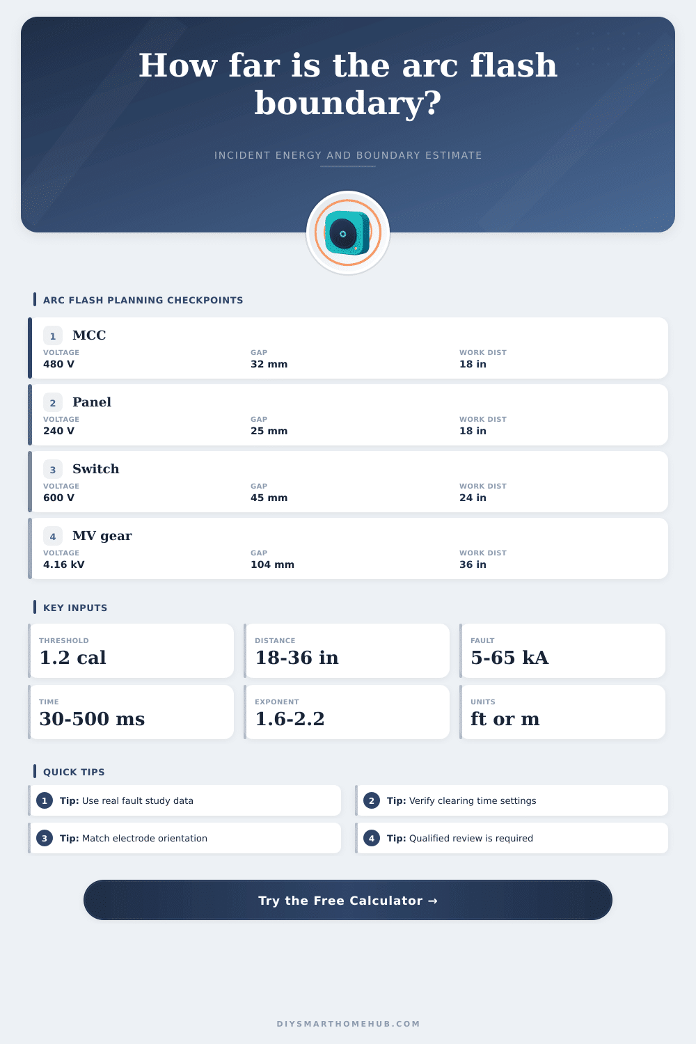
| 240V panelboard | 240 V | 10 kA | 60 ms | 18 in / 0.46 m | Lower voltage enclosed panel check |
| 480V panelboard | 480 V | 35 kA | 100 ms | 18 in / 0.46 m | Common low-voltage distribution panel |
| 480V MCC bucket | 480 V | 42 kA | 80 ms | 18 in / 0.46 m | Motor-control enclosure with vertical electrodes |
| 480V switchgear | 480 V | 65 kA | 120 ms | 24 in / 0.61 m | Main gear with higher fault level |
| 4.16kV switchgear | 4,160 V | 25 kA | 150 ms | 36 in / 0.91 m | Medium-voltage metal-clad cubicle |
🔌Electrode configuration table
| Code | Configuration | Typical use | Model effect | Default exponent |
|---|---|---|---|---|
| VCB | Vertical electrodes in box | Panelboards and switchboards | Focused energy in enclosure | 1.85 |
| VCCB | Vertical in box with barrier | Shrouded low-voltage gear | Higher confinement factor | 1.75 |
| HCB | Horizontal electrodes in box | Drawout gear and lineups | More direct outward plume | 1.65 |
| VOA | Vertical electrodes open air | Outdoor bus or exposed lugs | Less enclosure concentration | 2.00 |
| HOA | Horizontal electrodes open air | Outdoor horizontal conductors | Open but directional plume | 1.90 |
📐Formula and sensitivity table
| Calculation item | Formula used here | Increasing input does this | Planning caution |
|---|---|---|---|
| Arcing current | Iarc = Ibf x arc factor | Raises normalized energy | Also changes actual breaker clearing time |
| Incident energy | IEwd = base x Iarc x time x factors | Raises energy linearly in this estimator | Use a real IEEE 1584 study for final values |
| Distance decay | IE(D) = IEwd x (WD / D)^x | Higher exponent lowers distant energy faster | Exponent must match equipment and electrode geometry |
| Boundary distance | D = WD x (IEwd / 1.2)^(1/x) | Grows when IEwd exceeds threshold | Round up and follow site safety rules |
🏭Typical boundary scenario table
| Scenario | Input pattern | Energy driver | Boundary signal | Use this calculator to check |
|---|---|---|---|---|
| Fast LV panel | 480 V, 25 kA, 50 ms | Fault current moderate, time low | Often shorter boundary | Verify arcing current trips instantaneously |
| Delayed main gear | 480 V, 65 kA, 300 ms | Clearing time dominates energy | Boundary grows quickly | Protective-device curve at arcing current |
| Open-air bus | 600 V, 20 kA, 120 ms | Lower enclosure factor | Energy disperses faster | Correct open-air electrode selection |
| Medium voltage | 4.16 kV, 25 kA, 150 ms | Voltage and working distance are higher | Boundary can be wide | Use equipment-specific MV data |
💡Practical calculation tips
You stand in front of a humming electrical panel ready to tighten a loose connection. Onscreen sits an arc flash boundary distance calculator. It waits for data point that will mean either a minor burn or a life-changing wound.
Personal protective equipment is something most electrician are aware of, though few understand the underlying physics of PPE ratings until after it’s too late. Seconds, inches can separates life from death. At its heart is idea of incident energy. What does that even mean? Essentials it’s the amount of heat sent from an electrical arc at a certain distance.
What is Incident Energy?
You may be thinking: The bigger the voltage, the more dangerous it is, right? Well, not exactly. Clearing time are also important. A slow-breaking low-voltage system will release greater amounts of total energy compared to a fast-clearing high-voltage trip.
By entering both values (the clearing time and the fault current), the calculator perform all the complicated math so that you can concentrate on understanding what these figures mean in your work environment. It turns invisible electrical characteristics into a physical barrier protecting humans.
The voltage is the set up. The arcing current factor is what matters. What you read on a study report is available bolted fault current. But the arc has resistance, so it draws less current. This is estimated with a factor that also depends on equipment types. Some electrode are oriented different than others inside some equipment. Some equipment have a different internal geometry (for example a motor control center acts differently than a simple panelboard). Plug the max fault in, don’t worry about how much it might reduce and you skew everything. That is where people make mistakes.
The strongest thing you can control is clearing time. An incident that takes a tenth of a second versus a half second rocket the incident energy up. And as the calculator demonstrates, boundary distance changes a lot based off this value. A modest delay will bump safe zone from two feet out to five feet. That’s what makes selective coordination such a big deal. It doesn’t just protect equipment, it restricts human exposure time, because that’s what happens if you’re standing within a few feet of someone.
There’s also a practical limitation on working distance. If you have a door open, you’re typically about eighteen inches from the source. The tool will use that as the reference point for incident energy. It will then scale back to the boundary point where the energy falls below 1.2 calories per square centimeter. That’s the NFPA 70E standard for second degree burns. Why? Because it’s a physiological limit. It’s not some made up number.
Knowing this make it easier to understand why the boundary isn’t some sort of suggestion. It’s a hard stop for people who aren’t qualified.
It’s not just the electrode spacing: It’s also their arrangement. Horizontal electrodes in free space behave different than vertical electrodes enclosed in a box. And this is where distance exponent comes into play. The higher the exponent the quicker the energy drops off with distance. This detail distinguishes a rough guess from thoughtful engineering judgment.
The geometry of a particular situation determine whether to use a high or low exponent. How do you know? Match the model to the real-world conditions within that enclosure, as described in the reference table found on the page.
So don’t take these numbers as definitive. Arc flash studies are complex; changing conditions of equipment, room temperature, etc., will alter the results. But this is a screening tool. It provides some insight into how those three factors, distance, time, and current, balance against each other. This draws your attention to where the risk is highest, allowing you to focus your mitigation plans to match.
Let it force you to question your assumptions before a trained professional labels the final version for you. Because safety isn’t about using the proper calculator; it’s about learning to ask the correct question regarding the nature of electrical energy when things go wrong. Ultimately, all we’re looking for is to remain on the far side of that line where physics kills.
That’s why you honor the limit; it’s why you know what produces it. The math spits out a number and your precaution preserves you. It would of been better if you knew sooner.