EMT Offset Bend Calculator
Plan a two-bend EMT offset with bend multiplier, shrink per inch, conduit gain, mark locations, and obstruction clearance checks.
📌Quick Bend Presets
⚙Bend Inputs
EMT offset layout
Enter bend data to calculate mark positions.
📏EMT Bender Spec Grid
Bender radius and hook values vary by tool. The calculator uses editable planning allowances so the marks can match the bender in your hand.
📊Offset Bend Angle Reference
| Angle | Multiplier | Shrink per inch | Best use |
|---|---|---|---|
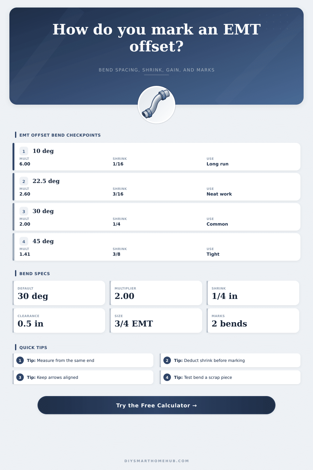
| 10 degrees | 6.00 | 1/16 in | Long gentle offsets where space is available. |
| 15 degrees | 3.86 | 1/8 in | Neat visible runs with moderate bend spacing. |
| 22.5 degrees | 2.60 | 3/16 in | Common field compromise for panels and racks. |
| 30 degrees | 2.00 | 1/4 in | Fast layout because spacing is twice the offset. |
| 45 degrees | 1.41 | 3/8 in | Tighter offsets when the run has limited length. |
| 60 degrees | 1.15 | 1/2 in | Very tight offsets with more bend severity. |
🛠EMT Size And Bender Planning Table
| EMT size | Outside diameter | Planning radius | Typical hook allowance |
|---|---|---|---|
| 1/2 in EMT | 0.706 in | 4.0 in | 5 in |
| 3/4 in EMT | 0.922 in | 5.0 in | 6 in |
| 1 in EMT | 1.163 in | 6.5 in | 8 in |
| 1-1/4 in EMT | 1.510 in | 8.5 in | 11 in |
📝Common Offset Layouts
| Offset height | 10 degrees | 30 degrees | 45 degrees |
|---|---|---|---|
| 2 in | 12 in spacing | 4 in spacing | 2.8 in spacing |
| 4 in | 24 in spacing | 8 in spacing | 5.7 in spacing |
| 6 in | 36 in spacing | 12 in spacing | 8.5 in spacing |
| 8 in | 48 in spacing | 16 in spacing | 11.3 in spacing |
🔍Marking And Clearance Checks
| Check | Formula | What it means | Field action |
|---|---|---|---|
| Offset height | Max(target, obstacle + clearance + radius) | Centerline rise clears the object. | Increase height if clearance is negative. |
| Bend spacing | Offset x multiplier | Distance from first bend mark to second. | Use same tape direction for both marks. |
| Shrink | Offset x shrink rate | Amount the offset pulls the far end back. | Deduct from the first mark when locating an object. |
| Run clearance | Offset / tan(angle) - width | Horizontal room inside the raised section. | Use a gentler angle for wider obstacles. |
💡Two Practical Tips
Anyone who’s attempted to run rigid conduit around a structural beam has been frustrated by lack of space. Now, you’ve got one of those little gaps on a building. You pull your tool out of the truck and suddenly geometry becomes difficult.
In most cases, it isn’t the bending action that frustrates electricians; it’s the math associated with making marks where you want the conduit to be placed. Those marks are needed because you want the conduit to clear the obstruction. If you do it incorrectly, then chances are you’ll have it too far back from wall or too high.
Why You Should Use This Conduit Calculator
To get the offset correct, you need to understand how metal react to the force being applied and use some trigonometry. Most folks would rather leave that math to a digital helper. That’s where our calculator comes into play (the one up top). But before trusting any result it gives, it helps to know what those numbers mean.
The key ingredient here? That’s the multiplier which indicates how far horizontally you must go to get that much vertically. For example, a thirty-degree bend carries a multiplier of two. This is a popular choice on the job site: The math is simple enough that you can do it in your head with a wrench in your hand. You’ll need eight inches between your bends to get four inches of rise.
41 Degrees. This reduces its footprint but sharpens its curve. That steeper turn create greater strain on the conduit’s walls. Not only that, but it complicates pulling wire through later on. So, on one hand, you save space; on the other hand installing gets difficult.
The other trap the novice always falls into is Shrink. As you bend conduit into an offset, you lose overall length in the run. Even if it looks like it should of been the same distance as straight line distance, it’s not. The calculator takes care of that for you by allowing you to remove shrink from whatever mark position you start at.
Shrink doesn’t leave much room for error. Especially if you’re going around a panel door or junction box, you can’t have a half-inch error caused by forgetting about shrinkage. You subtract the shrink amount (calculated from angle and height) and measure backwards from the obstruction. That’s the spot where your first bend line go.
It sounds counterintuitive; I mean why would you mark farther out when you want to go closer? But the math require it.
There’s one other part of rough estimates that people often overlook: Clearance. Sure, maybe you can calculate exactly how much offset is required to clear a pipe. But what about room for your hand? Will there be space for conduit runs that cross behind it sometime in the future? The tool has an additional clearance value that you can plug in. That way, your end result isn’t just theoretically accurate but practically useful as well. It forces you to consider not only theoretical line on paper but actual install environment.
A negative clearance sign from the calculator indicates you’re planning a bend that won’t occur physically. Either change the obstacle or bump up the offset height.
But then there’s oddness from the bender itself. Each tool bends to a different radius, which means they also bends at a different length from the hook. That changes the position of the arrow relative to your mark. There are fields in the calculator for hook allowance so you can factor in what bender you happen to be holding instead of relying on textbook (and therefore generic) numbers. You’d still do well to test a scrap piece of EMT before going for the actual run. A bender dropped one too many times, shaky hands after a long day, no algorithm will compensate for those.
Offsetting involves understanding how distance, angle, and different materials behaves with each other. You should do what works rather than merely trying to force metal around. Because the reality is that the offset tool doesn’t go where it does because it’s hard wired to be forced. It goes there because it fits in a real world where things has walls and pipes and limited space and it travels along a geometrical path.
If you know why the multiplier depends on the angle, suddenly this isn’t some black box tool anymore. It’s confirmation of what YOU know is going on. This allows you to double check the clearance and see how it makes sense. That’s what separates a pro install from just a quick fix.