Underfloor Heating Pipe Spacing Calculator
Size hydronic UFH pipe spacing from room heat loss, floor finish resistance, surface temperature limits, loop length, and water temperature so each zone has a realistic spacing target.
📌UFH spacing presets
Spacing recommendation
Results update after calculation.
📐Room, floor, and spacing inputs
📊Spacing and output quick specs
📋Reference tables
| Pipe spacing | Pipe density | Typical output range | Best use |
|---|---|---|---|
| 75 mm / 3.0 in | 13.3 m per m² | 85 to 110 W/m² | Bathrooms, glass edges, low water temperature |
| 100 mm / 3.9 in | 10.0 m per m² | 75 to 100 W/m² | High-output rooms and perimeter bands |
| 125 mm / 4.9 in | 8.0 m per m² | 65 to 90 W/m² | Kitchens, heat pump systems, exposed rooms |
| 150 mm / 5.9 in | 6.7 m per m² | 55 to 80 W/m² | Standard living areas with tile or vinyl |
| 175 mm / 6.9 in | 5.7 m per m² | 45 to 70 W/m² | Moderate-load rooms and insulated slabs |
| 200 mm / 7.9 in | 5.0 m per m² | 35 to 60 W/m² | Bedrooms and low-loss interior rooms |
| 250 mm / 9.8 in | 4.0 m per m² | 25 to 45 W/m² | Background heat in very low-load zones |
| 300 mm / 11.8 in | 3.3 m per m² | 20 to 35 W/m² | Only where heat loss is minimal |
| Profile | Heat loss | Spacing tendency | Notes |
|---|---|---|---|
| Very low loss | 35 W/m² | 200 to 250 mm | Interior rooms or strong fabric performance |
| New build | 45 W/m² | 175 to 200 mm | Works well with low water temperature |
| Good retrofit | 55 W/m² | 150 to 175 mm | Common design starting point |
| Average exterior | 70 W/m² | 125 to 150 mm | Check floor finish resistance carefully |
| High loss | 85 W/m² | 100 to 125 mm | May need perimeter zoning |
| Glazed exposed | 105 W/m² | 75 to 100 mm | Surface cap may limit UFH-only output |
| Finish | R value | Derate | Spacing effect |
|---|---|---|---|
| Tile or concrete | 0.01 m²K/W | 0.97x | Allows wider spacing |
| Vinyl or linoleum | 0.05 m²K/W | 0.88x | Usually standard spacing |
| Engineered wood | 0.10 m²K/W | 0.78x | Often needs closer spacing |
| Laminate with underlay | 0.12 m²K/W | 0.72x | Check underlay rating |
| Low-tog carpet | 0.15 m²K/W | 0.62x | Use closer spacing |
| High-tog carpet | 0.22 m²K/W | 0.48x | May be output-limited |
| Pipe OD | Typical loop | Min radius | Use case |
|---|---|---|---|
| 12 mm | 50 to 70 m | 60 mm | Low-profile overlay panels |
| 14 mm | 60 to 80 m | 70 mm | Retrofit boards and small zones |
| 16 mm | 80 to 100 m | 80 mm | Common UFH floor loops |
| 17 mm | 90 to 110 m | 85 mm | European PEX or PERT systems |
| 20 mm | 100 to 120 m | 100 mm | Large slab loops with lower resistance |
| Mean water | Best fit | Spacing cue | Limit check |
|---|---|---|---|
| 28 to 32 C | Passive or very low loss | 100 to 150 mm | Needs excellent fabric |
| 33 to 37 C | Heat pump friendly | 100 to 175 mm | Watch carpet derate |
| 38 to 42 C | Typical mixed UFH | 125 to 200 mm | Usually below surface cap |
| 43 to 47 C | Retrofit or high loss | 75 to 150 mm | Surface cap may govern |
| 48 C plus | Edge cases only | Design review | Blend down before UFH |
💡Practical spacing notes
If the target heat loss requires a floor surface above the room limit, closer pipe spacing alone cannot solve the design. Reduce heat loss, lower floor resistance, add an edge zone, or use supplementary heat.
Very close spacing raises pipe density quickly. The calculator checks loop count after adding supply and return tails, so the recommended spacing is tied to a realistic manifold layout.
The second error most people commit with underfloor heating: “More pipe = more heat.” No! More pipe mean more waste, more hot spots, and colder corners.
That’s because proper sizing of your loop isn’t so obvious; it’s about finding that balance between thermal resistance (insulation) and the room’s actual heat load. Before you cut one inch of PEX, you should of know roughly how much heat the floor will be able to give off… and for that, there’s no substitute other than doing the math. Plug in your room dimensions/insulation values into the calculator above, and it’ll do the math for you. You won’t have to guess at conversions or coefficients, which is what trips up most DIYers.
Why More Pipes Do Not Mean More Heat
First examine the floor finish… It’s where most designs fall apart. Stone and tile conduct heat. They transfer warm water from the pipe to your toes without much resistance. High-tog-pile carpet acts like a thermal blanket. It captures that warmth below ground and makes you have to turn the water temp way up just to get a little comfort.
To account for this, the tool includes reduction factors. So if you plan on using carpet, you’ll see the calculator recommend tighter spacing between pipes (or, worse yet, warning you that you’re unlikely to reach your desired output). There is not even an option. No matter how dense your pipes are, the physical barrier of a plushy rug cannot be defeated.
Another consideration is water temperature. Efficient hydronic systems runs at low temperatures… Exactly why they work so well. If possible, you’d like the average water temperature to be around thirty-five degrees Celsius. This is where heat pumps excel, and they quickly become less efficient when pushing temps above that level.
The table on the page spells it out: the interplay between water temp and spacing. If you can get away with tighter spacing, you’ll have more leeway for keeping water temps down without losing the heat-loss battle. It’s an install-labor vs. It is a long-term efficiency tradeoff.
Physics and plumbing intersect at loop length. To ensure proper water flow through each loop you want them to be equally long or balanced. That means a loop with 40 meters will heat up faster then the one with 80. You’ll have trouble getting everything stable. This calculator estimates your loop count and spacing based off the size of the room and the distance from the manifold to the end of the heated zone (tail). Note these figures. Going beyond normal does not help because it creates more friction loss, which could affect the outside parts of the loop. Where possible try to make the loops even when the geometry permits.
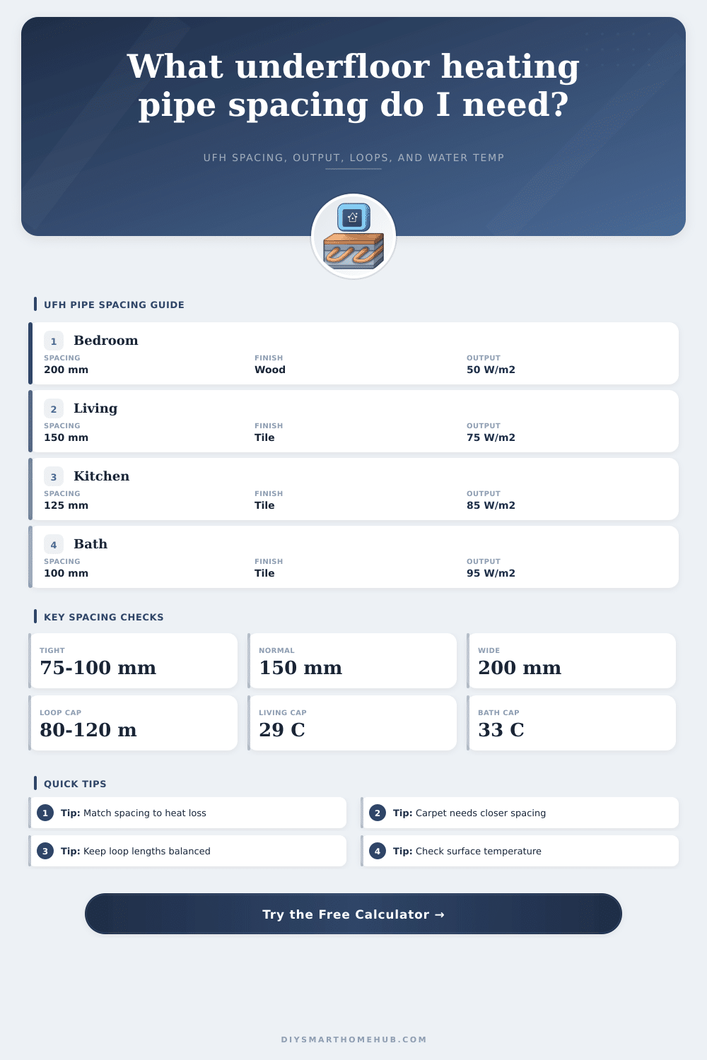
Then, nobody notices this problem until somebody complains: “my feet burn”. Living areas usually cap out at twenty-nine degrees Celsius for comfort. To be generous we’ll say bathrooms can be a bit hotter, and reach a max of thirty-three degrees, since people don’t stand on them barefoot for very long. When you plug in the size of the space, the tool tests whether your proposed output would exceed those safety margins. If so, you have to either adjust down the total heat loss of the room (which is what people are getting wrong) or accept additional heating.
Closer spacing doesn’t help because closer spacing isn’t enough by itself. The mistake people make is thinking they can just brute force their way out of bad insulation by laying down even more pipes. So consider the spacing (pitch) as being how clear the picture of heat is. If it’s just a little bit of heat loss from a well-insulated bedroom, then two-hundred-millimetre spacing will do nicely: cheap, quick installation; no fuss. But if it’s a kitchen with loads of thermal demand, or a glazed extension, you need the closer one hundred millimetres to ensure even distribution without hot bands. What you’re after is a consistent level of warmth over the whole surface of the floor. You want gradual warmth, not some sort of temperature patchwork quilt.
In short: Underfloor heating takes time. Patience. Precision. A slow form of heat from thermal mass instead of an instant burst of energy. The spacing matters; it means you won’t be adjusting thermostats as much, but will instead enjoy the warmth of the room. And the figures in the tool are there to give you a visual reminder of where to strike that balance before laying down boards or pouring concrete. Let the numbers guide your hand, trust the physics, and defer to the floor finish.