⚡ Subpanel Wire Size Calculator
Estimate feeder conductor size, equipment ground, neutral size, ampacity margin, voltage drop, and a conduit planning note for common garage, workshop, shed, and whole-home subpanel feeders.
Enter one-way feeder distance from the main panel to the subpanel. The calculator checks ampacity first, applies temperature/raceway derating, then upsizes if voltage drop needs a larger conductor.
Calculated feeder sizing will appear here.
Full Calculation Breakdown
| Conductor | Circular mils | Copper amps | Aluminum amps | Planning note |
|---|---|---|---|---|
| 10 AWG | 10,380 | 30 A | 25 A | Small equipment ground or short low-amp feeder |
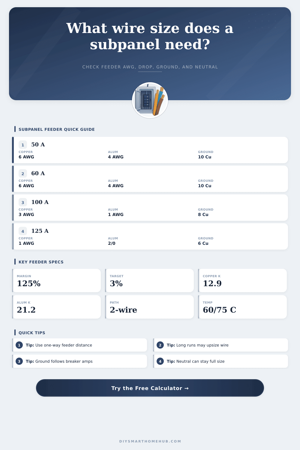
| 8 AWG | 16,510 | 50 A | 40 A | Common 40 A to 50 A copper feeder range |
| 6 AWG | 26,240 | 65 A | 50 A | Often used for 60 A copper planning |
| 4 AWG | 41,740 | 85 A | 65 A | Long 60 A run or moderate aluminum feeder |
| 3 AWG | 52,620 | 100 A | 75 A | Typical 100 A copper planning size |
| 2 AWG | 66,360 | 115 A | 90 A | Long 100 A copper or 90 A aluminum planning |
| 1 AWG | 83,690 | 130 A | 100 A | Common 100 A aluminum planning size |
| 1/0 AWG | 105,600 | 150 A | 120 A | Large detached garage or shop feeder |
| 2/0 AWG | 133,100 | 175 A | 135 A | 125 A aluminum with headroom |
| 3/0 AWG | 167,800 | 200 A | 155 A | 150 A class aluminum planning |
| 4/0 AWG | 211,600 | 230 A | 180 A | Large feeder with voltage-drop headroom |
| Feeder breaker | Copper ground | Aluminum ground | Neutral model | Calculator use |
|---|---|---|---|---|
| 15 A to 60 A | 10 AWG Cu | 8 AWG Al | Usually full-size or load-sized | Ground follows breaker, not distance |
| 70 A to 100 A | 8 AWG Cu | 6 AWG Al | Neutral checked from load share | Upsized when drop or neutral load requires it |
| 110 A to 200 A | 6 AWG Cu | 4 AWG Al | Large mixed loads often stay full-size | Calculator never sizes below load share |
| 225 A to 300 A | 4 AWG Cu | 2 AWG Al | Engineering review range | Planning reference only |
| 350 A to 400 A | 3 AWG Cu | 1 AWG Al | Large service-style feeder | Use detailed code review |
| Feeder method | Common conductors | Conduit note | Strength | Watch point |
|---|---|---|---|---|
| THHN/THWN copper in PVC | 2 hots, neutral, EGC | PVC is nonmetallic, needs EGC | Good corrosion resistance | Heat and fill derating still matter |
| XHHW aluminum in PVC | Larger aluminum sizes | More conduit room helps pulls | Lower weight on long feeders | Terminations must be rated for aluminum |
| THHN copper in EMT | Individual conductors | EMT may be grounding path where allowed | Durable indoor route | Bonding continuity is important |
| SER or feeder cable | Factory cable assembly | Conduit only where protection is needed | Fast straight-route planning | Installation location limits apply |
| Underground conduit | Wet-location rated wires | Schedule and burial details vary | Clean detached-building feeder | Use wet-rated insulation |
| Subpanel use | Breaker | Distance | Likely conductor range | Primary sizing driver |
|---|---|---|---|---|
| Backyard shed lights and outlets | 30 A | 40 ft / 12 m | 10 AWG to 8 AWG Cu | Ampacity first, drop second |
| Garage receptacles and small tools | 50 A | 75 ft / 23 m | 8 AWG to 6 AWG Cu | Voltage drop may upsize |
| Workshop with dust collection | 60 A | 110 ft / 34 m | 6 AWG to 4 AWG Cu | Drop and derating together |
| Detached garage with EV load | 100 A | 150 ft / 46 m | 3 AWG Cu or 1 AWG Al | Ampacity plus long-run drop |
| Barn or large shop feeder | 125 A | 220 ft / 67 m | 1 AWG Cu to 2/0 Al | Voltage drop dominates |
This calculator is for planning estimates. Final conductor size, wiring method, terminals, conduit fill, grounding, bonding, disconnects, and load calculation must be verified against the applicable electrical code and local authority requirements.
A feeder that passes ampacity can still need a larger conductor when the run is long. The voltage-drop circular-mil check is why a 60 A feeder can move from 6 AWG copper to 4 AWG copper on a detached-building run.
The equipment grounding conductor is based mainly on overcurrent rating, while the neutral is based on the calculated neutral load and should not be treated as the same shortcut.
Choosing an correct wire for a subpanel requires you to consider several different variable. The distance from the main electrical panel, the type of load that will be used at the subpanel, and the temperature of the terminal on the subpanel all must be considered. The wire must be able to safely carry the electrical currents that will be used at the subpanel, as well as prevent a voltage drop that may prevent the appliances or tool at the subpanel from functioning correct.
If the wire is not able to safely carry the current that will be used at the subpanel, or if the wire drop voltage at the subpanel, the wire may become warm, the breakers may trips, or the lights at the subpanel may dim when appliances with motors are start. To determine the correct size of wire for a subpanel, three primary input must be entered into a wire size calculator. You must enter the feeder breaker (the breaker at the main electrical panel that supplies power to the subpanel) size, the one-way distance between the main electrical panel and the subpanel, and the conductor material (either copper or aluminum).
How to Pick the Right Wire for a Subpanel
The breaker size will indicate the ampacity of the wire. The one-way distance between the main electrical panel and the subpanel will determine the voltage drop in the wire; the longer the distance between the main electrical panel and the subpanel, the more voltage will drop in the wire. The conductor material will impact the voltage drop in the wire; aluminum has higher resistance than copper, so aluminum wires will require more circular mils to allow for the same voltage drop as copper wire of the same gauge.
In addition to the three primary variables that impact the size of the hot (live) conductor, there are two additional variables to consider. The temperature of the terminals on the subpanel often will be rated to 60 or 75 degrees Celsius, while wires are rated to 90 degrees Celsius. Thus, if the subpanel has 60 or 75 degree terminal ratings, the ampacity of wires with 90 degree Celsius ratings cannot be utilized.
Additionally, other installation-related factors will also reduce the ampacity of the wire; if the wire will be exposed to an attic with high ambient temperatures, if the subpanel is located in an attic, or if many current-carrying conductor will be installed in the same conduit, the ampacity of the wire will need to be derated to account for these additional loads. Each of these variables will require the wire size to be increase by one or two sizes in the wire size chart. The neutral load percentage is another variable that needs to be considered for subpanels that will serve 120-volt outlet.
If the subpanel will serve many 120-volt outlets, the neutral wire will need to be able to carry nearly the same current as the hot wires. However, if the subpanel will be used for balanced 240-volt load, the neutral wire will not carry any current, so it will not be required. The size of the equipment grounding conductor is calculated differently then the size of the hot conductors at a subpanel.
The grounding conductor size is based upon the rating of the overcurrent device (main electrical breaker), while the size of the hot conductors is based upon the ampacity and voltage drop calculations. For instance, a 100-amp feeder may use 3 AWG copper for the hot conductors, but only 8 AWG copper for the equipment grounding conductor. Thus, a wire size calculator that determines the size of the equipment grounding conductor separately from the size of the hot conductors will ensure that the grounding conductor is not undersize.
There are different variables to consider for different installation scenario for subpanels. If a subpanel will be installed underground, the wire insulation will need to be rated for wet locations; additionally, there will be requirements for the depth at which the wire is bury. For long horizontal pulls, larger conduits are required even if the wires will fit within a smaller conduit.
Aluminum conductors will reduce the cost of long feeders from the main electrical panel to a subpanel; however, aluminum conductors have specific termination requirements that must be met, and those connections must be torqued to specific amount. Copper conductors cost more than aluminum conductors; however, copper conductors are easier to install because they can be pulled through tighter spaces, and they work with a greater variety of lug. Regardless of the specific scenario under which a subpanel will be installed, there is a specific pattern to follow to determine the wire size.
The ampacity of the wire must first be determined. Next, you must calculate the voltage drop in the wire. Finally, the derated ampacity of the wire must be determine.
For installations where the distance between the main electrical panel and the subpanel is short and the load that will be used at the subpanel is small, the ampacity and voltage drop calculations will be the same. However, for installations where the distance between the main electrical panel and the subpanel is longer than 100 feet, or for installations in which the subpanel will be located in a hot attic, the voltage drop and derating calculations will determine the size of the electrical feeders. This pattern can be used to determine the size of the electrical feeders for a garage shop, a backyard studio, or even for a detached building from the main electrical panel.
Following such a pattern will allow the electrician to ensure that the feeder supplying power to the subpanel will be cool, will deliver voltage to the electrical devices at the subpanel, and will satisfy the local inspector.