Fault Current Calculator
Estimate available short-circuit current at a service, panel, motor control center, or downstream smart-home equipment feeder using transformer kVA, percent impedance, source strength, conductor impedance, length, and motor contribution.
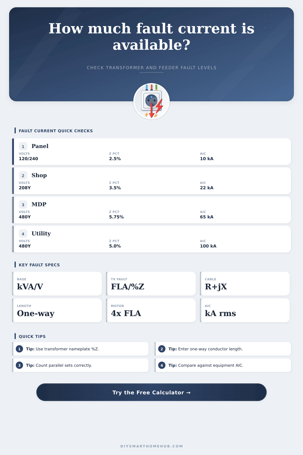
⚡Real fault-current presets
🔧Fault current inputs
📊Live electrical spec view
🧮Selected electrical/spec comparison grid
📘Transformer impedance reference
| Transformer class | Common voltage | Typical %Z | Fault-current effect |
|---|---|---|---|
| 25 to 50 kVA residential | 120/240 V | 1.7% to 2.5% | Very high fault current for small panels close to the transformer. |
| 75 to 150 kVA commercial dry type | 208Y/120 V | 2.5% to 4.5% | Panel AIC often becomes important on short secondary runs. |
| 225 to 500 kVA service transformer | 480Y/277 V | 4.5% to 5.75% | Common range for switchboards and distribution gear. |
| 750 to 1500 kVA utility padmount | 480Y/277 V | 5.75% to 6.5% | High available current; feeder impedance and AIC rating matter. |
🔌Conductor impedance reference
| Conductor profile | R ohm/1000 ft | X ohm/1000 ft | Best use in this calculator |
|---|---|---|---|
| #12 copper THHN | 1.98 | 0.054 | Small branch circuits and control power. |
| #6 copper THHN | 0.491 | 0.050 | Subpanels, small equipment, and EV branch circuits. |
| 1/0 copper THHN | 0.122 | 0.046 | Feeders where the run length still limits fault current. |
| 500 kcmil copper | 0.0258 | 0.040 | Large service feeders, switchboards, and parallel sets. |
| 4/0 aluminum XHHW | 0.101 | 0.048 | Common larger aluminum feeder comparison. |
| 500 kcmil aluminum | 0.0435 | 0.041 | Large aluminum service runs with lower resistance. |
⚙Motor contribution and AIC comparison
| Item | Typical multiplier | Calculator entry | Comparison note |
|---|---|---|---|
| Small induction motors | 3x FLA | Motor amps times 3 | Often used for light mechanical loads. |
| Typical induction motors | 4x FLA | Motor amps times 4 | Good default for many MCC and pump rooms. |
| High inertia motor groups | 5x to 6x FLA | Use conservative selector | Raises the momentary available current at the faulted bus. |
| Residential breakers | 10 kAIC | 10 kA selector | Common only when available current is demonstrably below rating. |
| Commercial panelboards | 22 to 42 kAIC | 22 or 42 kA selector | Used where transformer and feeder values exceed light-duty ratings. |
| Switchboards and service gear | 65 to 100 kAIC | 65 or 100 kA selector | Often needed near large utility transformers. |
📝Formula reference table
| Calculation step | 3 phase formula | Single phase formula | What it means |
|---|---|---|---|
| Transformer full-load amps | kVA x 1000 / (1.732 x V) | kVA x 1000 / V | Base current before applying percent impedance. |
| Transformer short-circuit amps | FLA / (%Z / 100) | FLA / (%Z / 100) | Available current at transformer terminals. |
| Feeder impedance | (R + jX) x length / sets | 2 x (R + jX) x length / sets | Single-phase faults use the outgoing and return path. |
| Downstream fault current | V / (1.732 x total ohms) | V / total loop ohms | Available fault at the selected panel or load end. |
💡Fault-current tip boxes
This calculator gives an engineering estimate for planning and comparison. Final short-circuit current ratings, series ratings, and protective-device coordination should be verified from manufacturer data and local electrical requirements.
Calculating the available fault currents is an important task for an electrician. Calculating the available fault current require more information than the nameplate of the transformer. The available fault current is the amount of short circuit current that can exist at a specific location in an electrical installation.
The impedance of the transformer, the length of the feeder circuit supplying the load, and the contribution of any motor in the installation can determine the available fault current. Every conductor run and every motor in the installation can play a role in altering the available fault current at a given location. The electrician can calculate the available fault current by first obtaining the kVA and the percent impedance of the transformer.
How to Calculate Available Fault Current
The kVA of the transformer and the percent impedance will establishes the maximum available current that can exist at the transformer secondary terminals. A lower percent impedance will allow more available fault current than a higher percent impedance. For example, a 75 kVA transformer with 2.5 percent impedance will have a higher available fault current than a 150 kVA transformer with 5.75 percent impedance.
It is also important to consider the available fault current of the utility power source that feed the transformer; the impedance of the utility source will decrease the available fault current that can reach the electrical equipment. The length and size of the feeder that supply the load will impact the available fault current. The resistance and reactance of the conductors will increases as the length of the feeder increases.
The available fault current calculator will use ohms per thousand feet of conductor and multiply that value by the length of the feeder run (one way) and the number of sets of parallel conductors. For example, a 65-foot run will have a higher resistance than a feeder run of the same diameter that will supply the load to a panel located right next to the transformer. The resistance of copper and aluminum conductor increases as the temperature increases.
Most tables of conductor sizes and resistivity values will use a conductor temperature of 75 degrees Celsius. Any changes in temperature will have a more greater impact on longer feeder runs. Motors that are part of the load will also impact the available fault current.
Motors will act as generators in the initial cycles after a fault occur. The load of all running motors must be entered into the available fault current calculator. You will enter a multiplier between three and six times the full load amp of the motors into the calculation tool.
The available fault current will be calculated based off the impedance of the circuit to the motors. The contribution of the motors will be added to the calculated current. Any available fault current calculation that ignores the motors will provide an optimistic value for the available fault current.
The output of the available fault current calculator is the amount of available symmetrical rms current at the location that is describe in the calculation tool. This value will be compared to the interrupting rating of the circuit breaker that is to be used at that location. The percentage of the margin between the available fault current and the interrupting rating will show if the circuit breaker will be able to handle the available fault current.
If the percentage margin is a negative number, the fault current will be higher than the rating of the circuit breaker. In this case, the circuit breaker must be of a higher electrical rating, or the manufacturer must verify the rating of the equipment. There are several variables in electrical installations that this available fault current calculation tool cannot capture.
For instance, the fault levels of the utility company can change if they reconfigure their power distribution feeders, or if they are adding generating facility to the electrical distribution system. The impedance of the transformer may be a range of values on the nameplate, rather than a specific impedance value. The temperature of the electrical conductors is not equally along each electrical conductor run.
The sets of parallel conductors are also not always balance with each other. These variables introduce uncertainty into the calculation. Thus, any final calculations for the electrical installation will be made with the information that this available fault current calculation tool provides, but will also incorporate data from the utility company and the electrical equipment manufacturer.
It is recommended to run the available fault current calculation tool at each service entrance to the electrical installation, at the location of the electrical panel that is the most distant from the service entrance, and at each location where motors are located. The available fault current will drop as the distance from the transformer increases, and the available fault current will decrease at locations where motors is located. The comparison of the available fault current at these different locations will show where in the installation available fault current drops to common electrical equipment rating, and where available fault current remains high enough to require 42 kAIC or 65 kAIC circuit breakers to provide protection for the electrical equipment.
This information will allow an electrician to focus there effort and attention when laying out an electrical installation job, and when reviewing an existing electrical installation.