Smart Flood Sensor Height Calculator
Calculate a practical probe height for smart leak and flood sensors by combining floor slope, drain relief height, pan lip depth, appliance clearance, and the water depth needed to trigger the selected sensor.
📌Real Placement Presets
Loaded preset: Water Heater Pan. The model checks whether the chosen probe height alarms before the pan lip or drain relief path wins.
⚙Height and Geometry Inputs
📟Sensor Spec Comparison Grid
📊Reference Tables
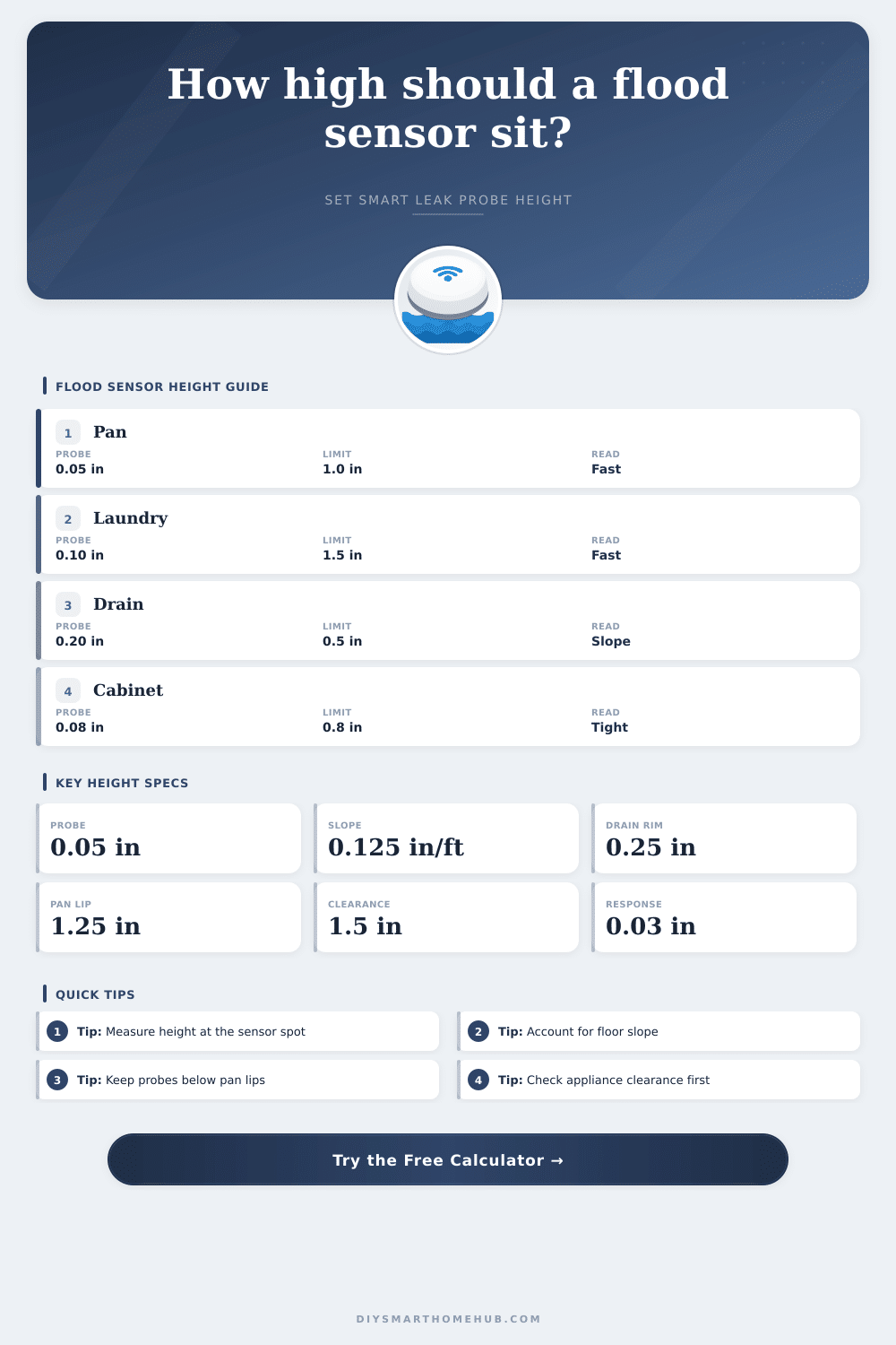
Probe height planning bands
| Contact height | Best use | Tradeoff | Result cue |
|---|---|---|---|
| 0.00 to 0.05 in | Pan, cabinet, appliance tray | Fastest alert, more nuisance films | Early alarm |
| 0.06 to 0.15 in | Laundry tray or slab | Skips tiny damp spots | Balanced |
| 0.16 to 0.35 in | Floor drain area | Slope can hide water at sensor | Check drain margin |
| Over 0.35 in | Sump or high-level warning | May miss shallow leaks | Late alarm |
Slope and drain effect
| Slope | At 4 ft | Drain rim | Sensor depth before relief |
|---|---|---|---|
| 0.00 in/ft | 0.00 in rise | 0.25 in | 0.25 in |
| 0.063 in/ft | 0.25 in rise | 0.50 in | 0.25 in |
| 0.125 in/ft | 0.50 in rise | 0.50 in | 0.00 in |
| 0.250 in/ft | 1.00 in rise | 0.75 in | 0.00 in |
Sensor style comparison
| Sensor style | Response film | Body height | Best placement |
|---|
Preset benchmark outcomes
| Preset | Suggested probe | Alert depth | Status |
|---|
💡Tip Boxes
Smart flood sensors will provide an early warning for you before a small leak can do damage to your floor or cabinet. A smart flood sensor only works correctly if the contact point of the smart flood sensor is placed at the correct height above the local floor level. If the contact point is placed too low, condensation droplets will trigger the detector.
If the contact point is placed too high, a leak may occur before the smart sensor triggers it’s alarm. Thus, there must be a balance found in the height of the smart flood sensor; the height of the sensor will determine whether the sensor is of any use to the kitchen or restaurant areas, or whether it may become a nuisance. The height that determines the function of a smart flood sensor is not the height of the smart flood sensor housing, but the height of the lowest point of the probe contacts of the sensor.
How to set the height of a smart flood sensor
Various factors relating to the area to be protected by the sensor determine the height of these contacts. For example, one factor is the slope of the floor. Even gentle slope can elevate the floor several tenths of an inch over a few feet.
Thus, if the smart flood sensor is placed on an incline away from the drain, the height of the sensor must account for this slope in its determination of the height at which the sensor will activate. The calculator that is provided takes care of the math for the user, allowing the user to simply enter the slope of the floor and the distance over which the slope exists. The same logic applies to determining the placement of the smart flood sensor near the drain.
In this situation, the height of the sensors contact point will likely be very low, if not 0 inches, as the water will reach that contact immediately. Another important factor is the texture of the floor. One smooth metal pan may hold a very thin film of water at its contact point, while another rough textured floor may leave the contact point dry despite the presence of water on that floor.
Thus, the height of the contact point will have to allow for an allowance for the water to wet the area that may be in contact with the sensor. This allowance will be a small amount, but it may be the difference between the sensor correctly detecting a slow drip of water and the sensor being triggered by water that has alredy escaped the area that is to be protected by the sensor. Next, the clearance of appliances from the floor may impact the height of the smart flood sensor.
For instance, a low-profile smart sensor with a cable probe may be able to be placed under the toe kick of a dishwasher, but a puck-style sensor may not be able to be placed under the toe kick of a dishwasher. Thus, the clearance calculation allows the user to determine whether the selected height of the sensor still allow for the sensor body to fit into the area to be protected. If the calculation reveals a negative number for the clearance of the appliance, then no amount of adjustment of the height of the sensor will allow for the sensor to fit into the location that is to be protected by the sensor.
Another important measurement for determining the function of the smart flood sensor is the escape margin. This measurement reveals the depth of water that remains between the contact point of the sensor and the lowest point at which water can leave the area to be protected. A healthy escape margin will allow the sensor to alert the kitchen or restaurant staff prior to the water reaching some threshold or lip that water can escape through.
An narrow escape margin indicates that the sensor will trigger only if all of the variables created the sensors activation are met; a negative escape margin indicates that the water will escape the area prior to the sensor becoming wet. The calculator accounts for these variables so that the user can make adjustments to the height of the sensor prior to installation of the sensor into the location that is to be protected. Many errors are made in installing smart flood sensors.
For instance, one common mistake is to purchase the smart sensor with the lowest reading of the height of the sensor’s contact point, this assumes that it will work anywhere. Another common mistake is to use the same height for the contact point as was used for another installation; they fail to consider if the floor slopes in a different direction to the installation site. Each of these mistake ignore the factors that impact the height of the contact point.
The reference tables that are provided on the page relate to the various heights of contact points for smart flood sensors. The tables indicate that the lowest heights for contact point will respond the fastest to water, but may trigger with condensation films on smooth floors. Heights that are slightly above the lowest heights will trigger less often due to condensation on the protected areas, but will still trigger prior to the water escaping the area.
These tables contain the same information as the calculator, but in tabular form. Many installation sites contain complications to the measurements. For example, refrigerators may be pulled out of the way for cleaning, which alters the floor elevation at which the appliance contacts the floor.
Similarly, the washing machine may flex when it is washing dishes and leave the floor at a different height than when the machine is resting on its pedestal. Additionally, the humidity in the kitchen and restaurant areas may cause a thin film of moisture to form on the protected floors; this moisture will not dry. These variables are why the calculator provides a recommended height for the contact point for the sensor; it is a starting point from which the height can be adjusted according to the actual installation site of the sensor.
The general goal in the installation of smart flood sensors is that the sensor should trip when the depth of the water is shallow. Thus, the kitchen or restaurant staff will be able to manage the depth of the water, and there will be minimal damage to the protected area. This goal is achieved through the height calculations, which ensure that the contact point is at the correct height for the sensors location.
Thus, once the contact point is correctly placed at the height that is calculated for that installation location, the sensor, the power source for the sensor, and the notifications that are generated will function correct.