Micro Hydro Power Calculator
Estimate net micro hydro watts, daily energy, penstock head loss, turbine match, and battery charging from measured water flow and vertical drop.
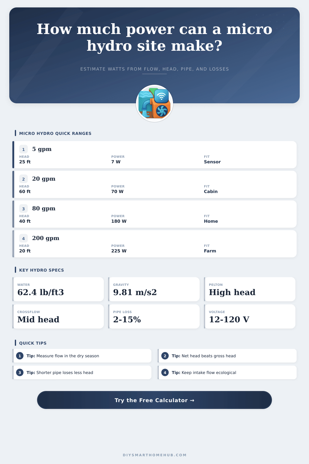
📌Real micro hydro presets
Presets are planning examples. Use measured dry-season flow, actual vertical drop, and the pipe route you can realistically maintain.
📏Calculator inputs
📊Micro hydro results
⚙Selected hydro spec grid
📘Turbine fit reference
| Turbine type | Best head range | Best flow style | Planning note |
|---|
🚰Penstock loss reference
| Pipe condition | Roughness used | Best use | Loss tendency |
|---|
💧Flow conversion table
| Flow | Liters per second | Cubic meters per second | Good head pairing |
|---|
🏠Preset output benchmarks
| Scenario | Flow and head | Pipe check | Delivered power |
|---|
✅Micro hydro sizing tips
Micro hydro power systems generates electricity from moving water. Micro hydro power systems can provide electricity even when the sun is not shine. A person can use a calculation tool to determine if a specific water source are suitable for the installation of a micro hydro power system.
The calculation tool will allow a person to calculate the amount of water that will be available from that source, as well as the amount of pressure that will be lost to friction from that water move through the systems penstock tubes. Knowing these factors will allow a person to determine if the water resource will produce enough power to be realistic in it’s use of power generation. The four primary feature that must be measured for the calculation of the power that a micro hydro system will produce are the flow, the gross head, the penstock length, and the inside diameter of the penstock tubes.
How to Check a Site for Micro Hydro Power
The flow of water is the amount of water that move past a specific point within a specific time period. The gross head of a system is the total vertical distance that the water will fall from the intake to the turbine. The length of the penstock is the length over which the water will travel from the intake point to the turbine.
Longer penstocks lose more power to friction. The inside diameter of the penstock is the diameter of the tubes through which the water moves. A small inside diameter will cause high velocity within the penstock, which will cause friction within the system.
These four features can be used in equations that calculate the net head that will be available to the turbine, as well as the total amount of watts that the system will produce. In addition to these features, a person must also select a turbine to use in the system. A Pelton runner turbine is used with high gross head and moderate water flow.
Crossflow runners work best with gross heads that are lower than Pelton runners and where the flow vary, such as in creeks. Propeller turbines require high volumes of water but do not require high gross head. Using a turbine that does not match the flow and gross head will cause the turbine to not produce the maximum amount of watts of potential energy.
The material from which the penstock tubes are made will impact the friction within the system. Smooth materials like HDPE or PVC tubing allow for low friction within the system. Rough materials like old steel or corrugated plastic will increase the friction within the system, which will reduce the watts produced by the system.
Using a larger inside diameter will allow for more space for the water to travel, which will reduce the friction within the penstock tubes. It is often better to use a larger penstock that produces less friction than to purchase a more efficient turbine. A person should measure the flow of the water source during the dry season to ensure that the system will produce power during all months of operation.
If only the spring flow is measured, the system may not provide power during the dry months of summer and autumn. In addition to measuring the flow, the flow during the driest part of the year should be measured to avoid purchasing equipment that cannot be utilized for long periods. Additionally, a person should also consider the amount of water required by the ecosystem in which the micro hydro system is installed.
This flow is called the bypass flow, and it is the amount of water that must remain in the environment by the power plant. A calculation tool will provide information about how much power is lost if water is not diverted into the penstock tubes. Head loss occur within a penstock system as water travels from the intake to the turbine.
The longer and narrower the penstock tubes, the higher the loss of head (and energy) that the system will experience. High velocities within the penstock will increase friction, which will lower the power of the system. Head loss can be reduced by altering the route of the penstock to be shorter, or by increasing the inside diameter of the penstock tubes.
A micro hydro power system is often connected to a battery. The voltage of this battery impacts the movement of electricity through the system. A 48 volt battery will move the same amount of watts as a 12 volt system, but the 48 volt system will use less current.
Using less current will produce less heat within the system and allow for smaller electrical wires. The power plant will experience some losses during the system, which need to be account for. These losses include losses within the rectifier, the wiring losses, and the time required to clean the intake site for the system.
A well-maintained system can achieve high availability. However, conservatively estimating these values will create realistic expectations regarding the performance of the system. The reference tables within the calculation tools will show the power of the system based on the flow and head of the system.
These tables will also show which type of turbine will best function within a system with those features. Because a micro hydro system will continuously produce power, the total amount of power that is produced over the course of a single month will be high. This is one of the main advantage of using a micro hydro power system.
A person should run the calculation a few time with different diameters for the penstock tubes. The best case scenario for a system will produce more watts than the worst case scenario. By changing a feature such as the inside diameter, a person can determine the extra cost of the system compared to the extra watts that will be produced.
A large change in watts with a small change in the inside diameter indicates that increasing the inside diameter is a good investment. A small change in watts with a large change in the inside diameter indicates that the inside diameter is a limiting factor in the creation of the system. A person should account for the losses of head and flow within the system and the dry-season flow of the water source before beginning to create a system.
The calculation tool will allow a person to determine the best components for the system. Once all of the calculations and decisions for the system are make, the system will produce usable electricity with low fuel costs and few moving parts.