WiFi Antenna Calculator
Size practical WiFi antenna elements from frequency, antenna style, material correction, feedline loss, connector loss, and transmitter power.
📌Real WiFi antenna presets
⚙Antenna inputs
Formula Breakdown
📊Spec grid
📶WiFi band wavelength reference
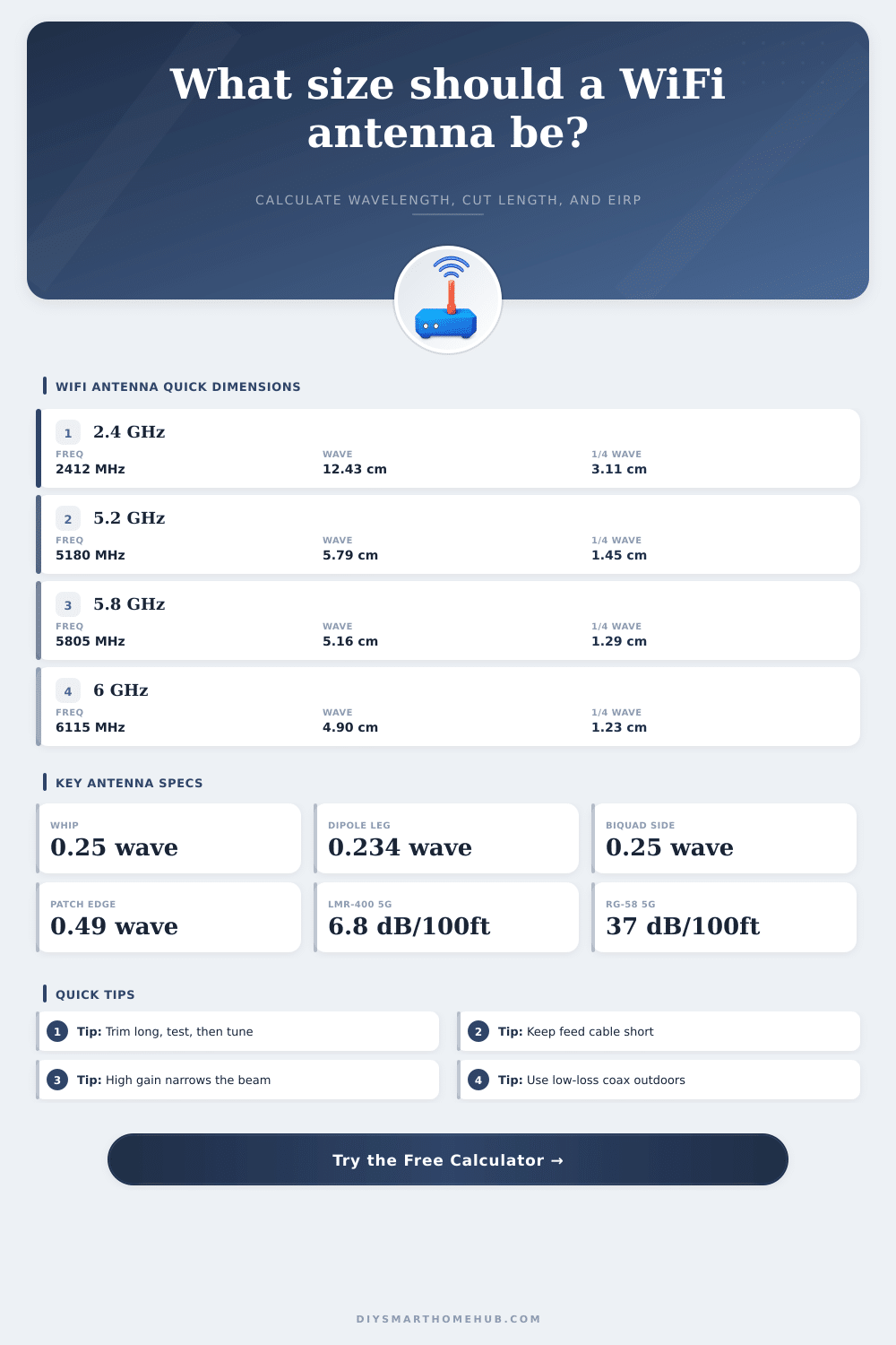
| WiFi use | Center frequency | Free-space wavelength | Quarter wave | Dipole leg at 0.95 factor |
|---|---|---|---|---|
| 2.4 GHz channel 1 | 2412 MHz | 12.43 cm / 4.89 in | 3.11 cm / 1.22 in | 2.76 cm / 1.09 in |
| 2.4 GHz channel 6 | 2437 MHz | 12.30 cm / 4.84 in | 3.08 cm / 1.21 in | 2.73 cm / 1.08 in |
| 5 GHz lower UNII | 5180 MHz | 5.79 cm / 2.28 in | 1.45 cm / 0.57 in | 1.29 cm / 0.51 in |
| 5.8 GHz upper band | 5805 MHz | 5.16 cm / 2.03 in | 1.29 cm / 0.51 in | 1.15 cm / 0.45 in |
| 6 GHz low channel | 6115 MHz | 4.90 cm / 1.93 in | 1.23 cm / 0.48 in | 1.09 cm / 0.43 in |
💡Antenna type comparison
| Antenna type | Main dimension used | Typical gain | Best smart-home use |
|---|---|---|---|
| Quarter-wave whip | 0.25 wavelength radiator | 2.1 dBi with ground plane | Router, sensor hub, short pigtail antenna |
| Half-wave dipole | 0.234 wavelength per leg | 2.15 dBi broad coverage | DIY access point or indoor coverage test |
| Biquad | 0.25 wavelength per square side | 10 to 12 dBi directional | Garage, gate, shed, or camera bridge |
| Yagi | Driven element near 0.475 wavelength | 9 to 13 dBi directional | Outdoor point-to-point camera or outbuilding link |
| Patch | Patch edge near 0.49 wavelength | 6 to 8 dBi panel beam | Wall AP, ceiling AP, focused room coverage |
| Coax collinear | 0.5 wavelength sections with cable factor | 4 to 6 dBi flatter pattern | Vertical coverage where height is available |
🔌Feedline loss reference
| Cable type | Approx loss at 2.4 GHz | Approx loss at 5.8 GHz | Use it when |
|---|---|---|---|
| RG-174 miniature | 52 dB per 100 ft | 78 dB per 100 ft | Very short pigtails only |
| RG-58 | 24 dB per 100 ft | 37 dB per 100 ft | Short bench tests, not long WiFi runs |
| LMR-100 class | 39 dB per 100 ft | 58 dB per 100 ft | Thin internal jumpers |
| LMR-195 class | 11 dB per 100 ft | 17 dB per 100 ft | Compact AP-to-antenna runs |
| LMR-240 class | 7 dB per 100 ft | 11 dB per 100 ft | Moderate runs with less loss |
| LMR-400 class | 3.9 dB per 100 ft | 6.8 dB per 100 ft | Longer outdoor WiFi antenna feeds |
🏠Common project size examples
| Smart-home scenario | Typical frequency | Useful antenna | Dimension to check | Loss detail |
|---|---|---|---|---|
| Single-room router antenna | 2437 MHz | Quarter-wave whip | Radiator length | Usually no external feedline |
| Apartment sensor hub | 2462 MHz | Half-wave dipole | Each leg length | Short RG-174 pigtail matters |
| Garage camera bridge | 5805 MHz | Biquad or cantenna | Loop side or probe | Use low-loss coax if outside |
| Yard gate camera link | 5745 MHz | Yagi | Driven element and directors | Connector loss changes link margin |
| 6 GHz room coverage test | 6115 MHz | Patch | Patch edge estimate | Cable losses rise with frequency |
✅Calculation tips
Designing a WiFi antenna require an understanding of the relationship between the frequency of the WiFi signal, the antenna style, and the length of the antenna. The length of the antenna are based upon the center frequency of the signal that the antenna will radiate. Antenna style is also important in that different antenna have different requirements for the length of the antenna.
For example, a quarter-wave antenna will have a length that is a quarter of the wavelength of the signal, while a dipole antenna will have a length that is half of the wavelength of the signal. Other factors that impact the length of the antenna include the shortening factor that the materials used to construct the antenna introduce. Additionally, the length of the antenna also must be shortened for the loss of signal that is introduced by the antenna cable and antenna connectors.
How to Make and Tune a WiFi Antenna
The calculator will provide the length of the antenna based off the frequency of the signal that the antenna is to radiate and the style of the antenna. The frequency of the signal is a critical factor in determining the length of the antenna. The higher the frequency, the shorter the wavelength of that signal.
For example, 2.4 GHz has a longer wavelength than 5 GHz, and 5 GHz has a longer wavelength than 6 GHz. Since the wavelengths of these frequencies are so small, even the slightest error in the length of the antenna will cause that antenna to not resonate at that frequency. Therefore, you should use the center frequency of the signal in the calculator, not the name of the signal band.
In order to calculate the total Effective Radiated Power (ERP) of the antenna, it is also necessary to account for the loss of signal that occur with the antenna cable and connectors. Cable loss is the reduction of signal strength as the signal radiates through the antenna cable. The longer the antenna cable, the more greater the loss of signal strength.
Connector loss is the loss of signal strength that occurs as the signal passes through the various connectors of the antenna system. The more connectors in the system, the greater the loss of signal strength. Additionally, the different types of cabling can also impact the loss of signal strength.
For example, thicker, low-loss cabling will allow more of the signal to travel through the cable than thin, miniature cabling. Thin miniature cabling is easier to route to the antenna, but if too long could remove all of the gain that the antenna provide. In addition to the variables that the calculator accounts for, there are other variable in the real world that will impact the performance of the WiFi antenna.
For instance, the metal and plastic housing that contains the antenna will impact the resonance of that antenna. Additionally, the ground plane that the user uses for the antenna will also impact the resonance of that antenna. For these reasons, it is necessary to cut the antenna elements to be slightly longer than the length calculated by the calculator.
The antenna elements can then be trimmed to the proper length while the antenna is being tested. Additionally, the placement of the antenna will also impact the signal that the antenna radiates. Antennas with high gain will have a narrow beam of signal that may not be directed towards the target WiFi device.
Therefore, while the EIRP figure will tell you the total power of the signal that the antenna radiates, it will not tell you if the signal will reach you’re device. Common mistakes when installing WiFi antennas may involve ignoring the signal loss due to the cable and connectors of the antenna. For instance, an individual may select a high-gain antenna that is efficient at radiating signal power, but use an antenna cable with a high signal loss, such as RG-174.
In this case, the strength of the signal may not reach the target device. Additionally, each connector in the system will contribute to the loss of signal strength. This is why it is important to account for each connector when building the system.
Furthermore, outdoor installations may experience additional signal loss due to exposure to the elements. Indoor installations may also experience signal loss if the antenna is routed near power line or metal elements in the environment. The calculator will ask for the transmitter power of the signal in the unit of dBm.
The use of dBm units will allow for the signal loss of the antenna cable and antenna connectors to be subtracted from the power of the transmitter, the gain of the antenna, and the resulting Effective Radiated Power (ERP) of the signal. The value of ERP will be used to determine the power of the signal that the antenna system radiates. By using the WiFi antenna calculator to determine the length of the antenna, the gain of the antenna, the signal loss of the antenna cable, the signal loss of the antenna connectors, and by taking the proper steps to install the antenna, it is possible to ensure that the signal radiated by the antenna will effectively reach the target device.
Additionally, by taking these steps, the WiFi link will remain stable.