K Factor Airflow Calculator
Convert balancing-hood pressure into corrected outlet airflow, solve the pressure needed to hit a target, or back-calculate the K factor for a diffuser, grille, louver, or fresh-air valve.
📌Quick balancing presets
This build centers on the manufacturer K factor method used in testing and balancing. It corrects for air density, multiplies by outlet count, and uses net free area to show whether the measured flow is moving quietly or pushing hard.
📏Measurement inputs
💡Live balancing notes
📊K factor results
Run the calculator to connect K factor, pressure, and outlet flow.
🔧K factor reference blocks
| Profile | Sample K | Quiet dP | Face band | What to watch |
|---|
| Standard K | 0.02 iwc | 0.05 iwc | 0.10 iwc | 0.20 iwc |
|---|
| Condition | Temp | Elev | Corr | Effect |
|---|
| Preset project | K | dP | Qty | Total flow |
|---|
If K and pressure say the diffuser is already near target but room airflow still feels weak, the issue may be throw, mixing, or how many outlets are sharing the same total branch flow.
A light-air reading at a warm, high site can understate real flow if you use the sea-level K relation without correction, especially on low-pressure valves and transfer openings.
The K factor method is an mathematical method of calculating airflow in a system. You use teh K factor method for two reasons. First, a manometer will give you a pressure reading, but not a reading of airflow in cubic feet per minute.
Second, the K factor method use a formula that allows you to calculate airflow based off the K factor of the system components and the square root of the differential pressure. The manufacturer of the components provides the K factor. You must use the K factor instead of pressure readings to accurately measure airflow through the components.
Using the K Factor to Measure Airflow
For example, low pressure reading can be caused by low airflow, but thin air at high elevations can also cause low pressure readings. The K factor will account for this and give you a true measurement of the airflow. Airflow do not scale linearly with pressure.
If you increase the pressure, the airflow will not increase in the same amount. For instance, if you increase the pressure by a factor of two, the airflow will increase by approximately a factor of 1.4. This relationship is important to understand when measuring high-K return grilles and low-K exhaust valves.
A small change in pressure will have a significant effect on airflow in high-K components, but a small change in pressure will have a minimal effect on low-K components. Air density plays a role in the accuracy of the K factor method. Air density changes with changes in temperature and elevation.
At sea level and 70 degrees Fahrenheit, the density of air is at its maximum. If the air is warmer, such as in a warm attic, the air density will be lower because air expand when it is warmed. If the elevation is high, such as 5,000 feet, the air will be less dense.
To account for these changes in air density, you can make density corrections for air temperature and air elevation. These corrections will increase the calculated value of cubic feet per minute by 10 percent or more. You need to consider the number of outlets that is connected to a hood or a branch of ventilation.
One hood can have many outlets. If you calculate the airflow for one outlet, you must multiply the airflow by the number of outlets in that branch to get the total airflow for that branch. You also need to consider the free area of the grilles or the louvers.
These components have frames and blades that dont allow for free movement of air through that component. The free area of the grilles or louvers is less than the total area of the face of those components. The free area dictates the face velocity of the components.
High face velocities will result in a noisy exhaust system. Therefore, you need to monitor the face velocity of these components. Each type of exhaust or return component will have a different K factor value and different requirements for the pressure in the system.
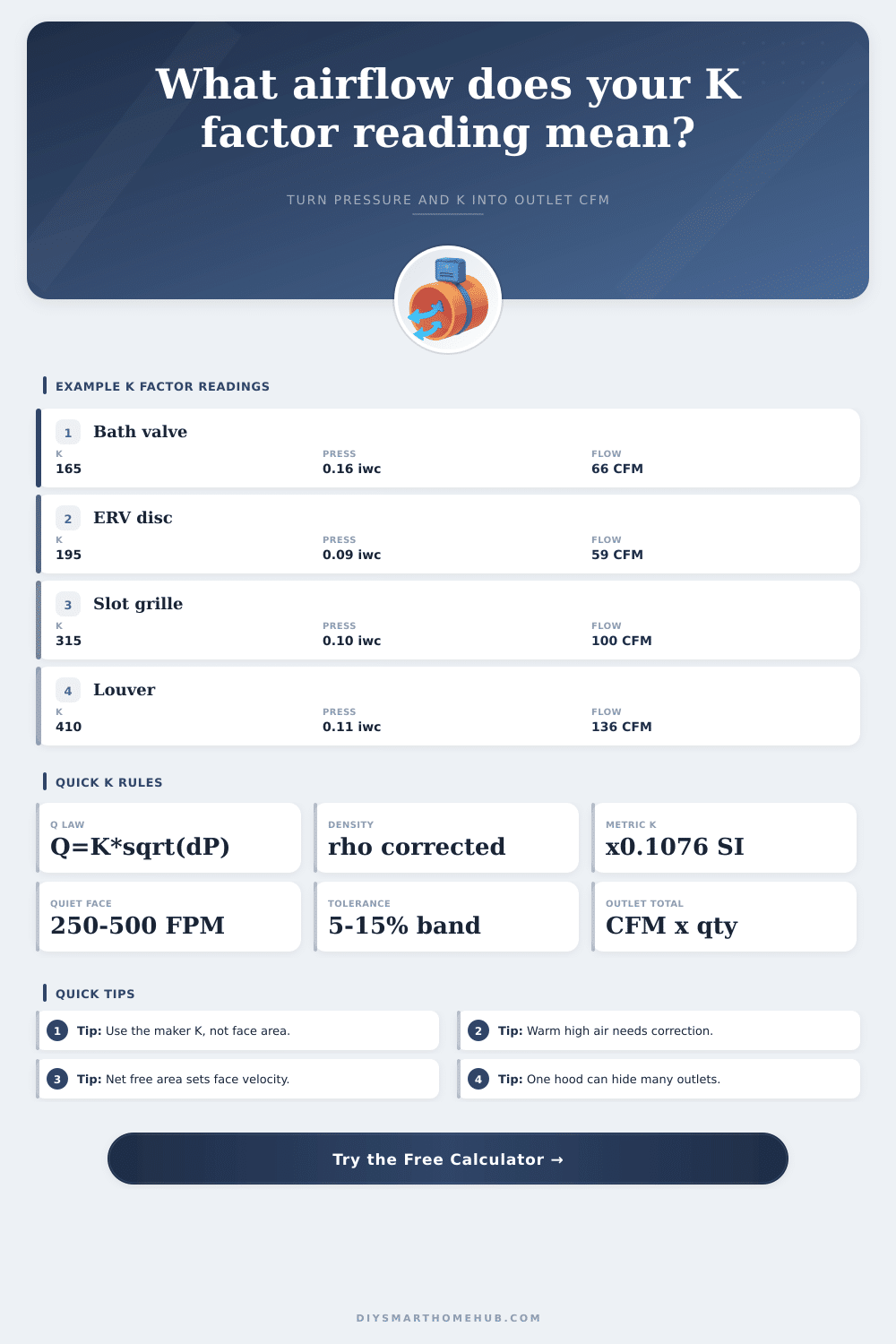
For instance, ceiling diffusers has a K factor of 200 and require low pressures of 0.03 inches to 0.10 inches of water column. Linear slots have high K factors, above 300, and also require higher pressures to create the desired amount of throw. Return grilles have high K factors because of the wide openings in those components but require very low pressures to move a large amount of air.
Exhaust valves in the bathroom is compact so require high pressures of 0.15 inches of water column. Each component should be in the correct pressure band to provide the target airflow without creating noise or hot spot in the system. A common mistake is to use the face area of the component as opposed to the K factor.
You use the face area to calculate an estimate of the velocity of the airflow through the component, but the K factor will give a more accurate measurement of the airflow. Another common mistake is to ignore the multiples of the outlets. If one outlet measures 60 cubic feet of minute of airflow and there are four outlets total, the total airflow will be 240 cubic feet per minute.
You must calculate the total airflow in the system to ensure that you are not overloading the makeup air system with supply air. The K factor can be used in two different ways. One way is to use the target airflow and the K factor of the component to calculate the required differential pressure to ensure that the dampers in the system can provide the required pressure for the target airflow.
The second use of the K factor is to use the differential pressure and the airflow to calculate the real K factor of a component that does not have a published K factor. When balancing the system with the manometer, you should aim for a tolerance of 5 to 15 percent. If the actual airflow of a component is within 10 percent of the calculated airflow, the system is considered balance.
To ensure that the system is balanced, you can take certain procedures when using the manometer. First, you must center the sensing tube in the exhaust opening. Second, the sensing tube must be sealed to ensure an accurate reading of the pressure in the system.
Third, every active outlet must be counted in the system. Fourth, the temperature and elevation of the location of the system should be noted in the reports of the balanced system. By using the K factor method according to the procedures mentioned, you can successfully balance the ventilation system and ensure that the pressure readings are converted to accurate numbers of cubic feet of minute of airflow.