Cable Tray Fill Calculator
Check whether a ladder tray, basket, or trough has enough room for low-voltage bundles, branch circuits, or battery cables while preserving reserve space for future smart-home expansion.
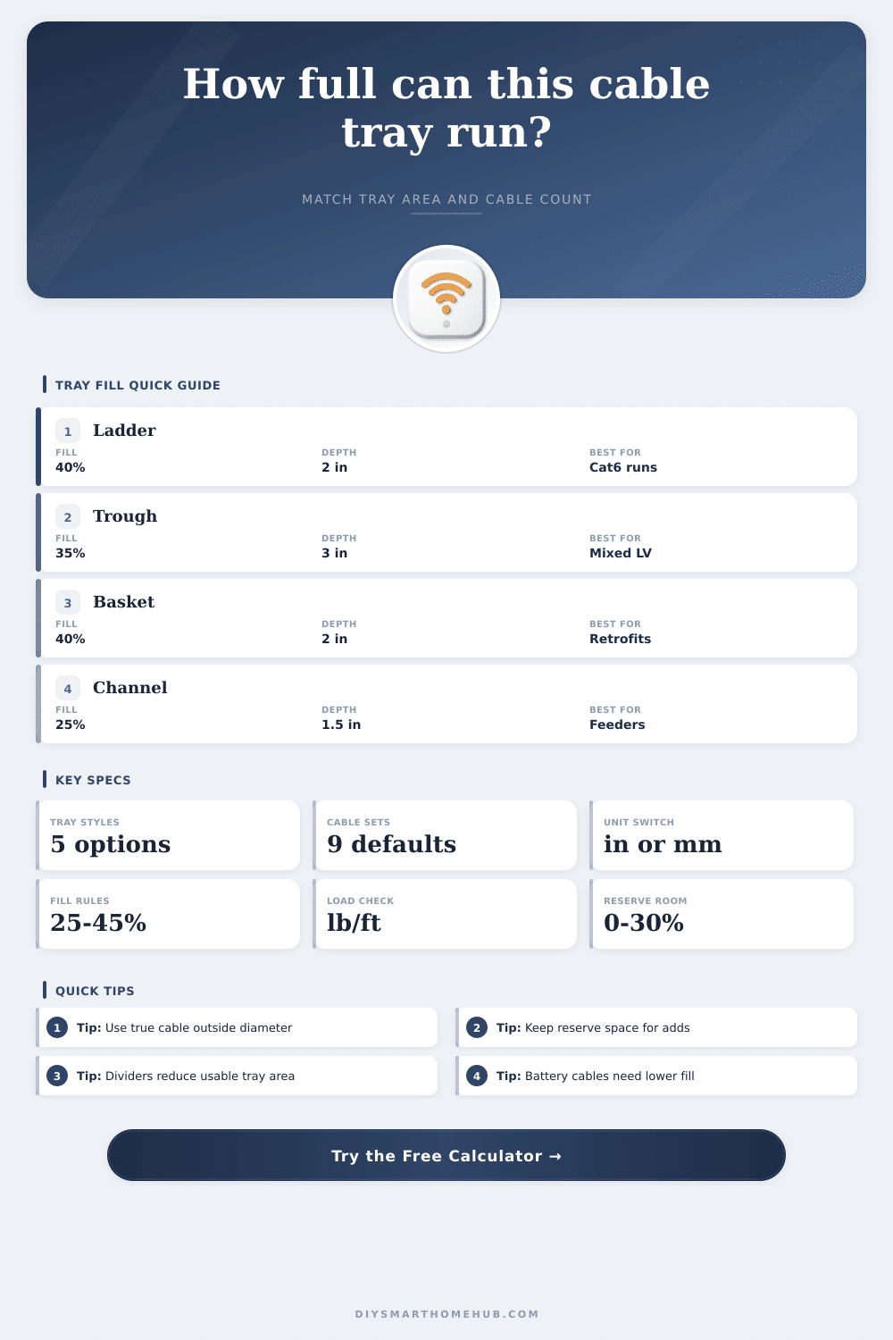
Tray fill is based on true cable outside diameter, the tray style reduction, service-class working fill, bundle packing, and the spare capacity you want to leave open for future drops.
Calculation Breakdown
| Service Class | Working Fill | Typical Cable Mix | Why It Stays Lower |
|---|---|---|---|
| Data and communications | 40% | Cat6, coax, fiber race bundles | Leaves room for airflow, re-pulls, and separation. |
| Security and controls | 45% | Alarm, access, thermostat, sensor loops | Small round cables pack tightly but still need service room. |
| Mixed low-voltage bundle | 40% | Data, speakers, control, cameras | Mixed diameters create voids and need cleaner management. |
| Mixed branch circuits | 30% | NM-B, MC, appliance feeds | Thicker jackets and heat call for more air space. |
| PV and battery DC | 35% | PV wire, battery links, control pairs | Higher current paths should not crowd each other. |
| Single-conductor feeder | 25% | Large one-conductor power feeders | Big cables and spacing rules limit how tightly they can sit. |
| Cable Family | Nominal OD | Metric OD | Weight / 1000 ft | Min Bend Radius |
|---|---|---|---|---|
| Cat6 UTP | 0.25 in | 6.4 mm | 28 lb | 8× OD |
| Cat6A F/UTP | 0.35 in | 8.9 mm | 46 lb | 8× OD |
| RG6 quad shield | 0.28 in | 7.1 mm | 36 lb | 10× OD |
| 18/4 security | 0.22 in | 5.6 mm | 24 lb | 8× OD |
| 16/2 speaker | 0.24 in | 6.1 mm | 31 lb | 7× OD |
| 12/2 NM-B | 0.43 in | 10.9 mm | 93 lb | 5× OD |
| 10/3 MC | 0.62 in | 15.7 mm | 184 lb | 7× OD |
| 2 AWG battery | 0.56 in | 14.2 mm | 240 lb | 8× OD |
| 4/0 feeder | 0.78 in | 19.8 mm | 515 lb | 12× OD |
| Tray Width | Nominal Area | 40% Fill Area | Approx Cat6 Count | Approx Cat6A Count |
|---|---|---|---|---|
| 4 in × 2 in | 8.0 in² | 3.2 in² | 65 cables | 33 cables |
| 6 in × 2 in | 12.0 in² | 4.8 in² | 98 cables | 50 cables |
| 12 in × 2 in | 24.0 in² | 9.6 in² | 196 cables | 100 cables |
| 18 in × 2 in | 36.0 in² | 14.4 in² | 294 cables | 150 cables |
| 24 in × 2 in | 48.0 in² | 19.2 in² | 392 cables | 200 cables |
| Project Scenario | Tray Setup | Cable Count | Suggested Service Class | Planning Note |
|---|---|---|---|---|
| 12-camera PoE hallway | 6 in ladder, 2 in rail | 12 to 20 Cat6 | Data and communications | Leave side space for future door stations or AP drops. |
| Whole-home AV rack | 12 in basket, 4 in depth | 40 to 80 mixed LV | Mixed low-voltage bundle | Mixed cable diameters waste more area than uniform Cat6 runs. |
| Garage EV + data tray | 12 in trough, 3 in depth | 6 power + 18 data | Mixed branch circuits | Reserve divider space whenever power and comms share a path. |
| Battery closet tray | 8 in ladder, 2 in depth | 4 to 8 large DC cables | PV and battery DC | Large conductors usually hit spacing and bend limits first. |
| Utility closet retrofit | 4 in channel, 1.5 in depth | 8 to 16 controls | Security and controls | Channel trays get crowded quickly once divider room is reserved. |
A tray can be under a basic percentage limit and still be a poor service tray. If you expect future cameras, speakers, sensors, or battery leads, leave real expansion space now.
Battery and feeder cables occupy depth quickly, need larger bend radii, and often force wider trays or separate lanes even when the pure area math still looks acceptable.
Cable tray fill is the measurement of how much space the cables will take up within teh tray. Many peoples will attempt to calculate the cable tray fill by measuring the width of the tray. However, calculating cable tray fill by sight often create errors.
If a person puts too much fill within a tray, the cables can become difficultly to service later on should additional cables need to be added to the system. Therefore, calculating the correct cable tray fill is necessary so that installers can easily install and service the cables easily in the future. There are various type of cable trays that is available for different needs.
How to Measure Cable Tray Fill
For example, ladder trays have open rungs that allow the heat to escape from the bundles of data cables. Another type of tray are wire basket trays, which are often used in retrofit projects since these trays can fit within the existing drop ceiling in an installation. Solid bottom trough trays are another type of tray; however, these trays will reduce the amount of space available for the cables since these trays are made to manage the amount of dust in a location.
Each type of tray will alter the equation that is used to calculate the cable tray fill since each type of tray has a different amount of usable area. The shape of the cables will also impact the calculation of the cable tray fill. Since cables is round, there will always be empty voids in between the cables.
These voids will increase the amount of space that the cables will take up within the tray. The different diameter of the cables will also increase the amount of space that the cables will use within the tray. Additionally, the calculation of the cable tray fill should use the true outside diameter of the cables rather than the nominal size of the cables from the manufactures specification sheet.
One of the primary reasons that a person must calculate the cable tray fill is to allow for heat dissipation from the power cables. The power cables will generate heat during the operation of the system. These power cables will need more space within the cable tray since the heat from these cables will need to dissipate.
If the power cables become too tight packed within the tray, the heat could cause the failure of these cables. Data and communication cables will also need to be able to dissipate heat, but they can be packed more close than power cables. For example, data and communication trays will be filled to 40 percent with cables, but the branch circuit will be filled to 30 percent so that there is more room for the heat to dissipate from the power cables.
Therefore, a person should leave enough space for the air to move and cool the cables within the tray. A person also needs to plan for the future of the system and the future capacity of the system. For this reason, extra space within the tray should be provided for the installation of new cables in the future.
If a person fills the tray with all of the cables needed for the current installation of the cables, there may not be time to add new cables to the system in the future. Therefore, the cable tray should be filled to approximately 75 to 85 percent of the target that is calculated for the design of the system. This percentage will allow for the installation of new cables in the future while avoiding wasting space within the ceiling or rack in which these trays will be installed.
The weight of the cables is one more factor to consider when a person is installing the tray. Many cables is heavy, and if these cables are not ignored in the installation of the tray, the tray could sag. The supports for the tray should be able to hold the weight of the cables.
If a person correctly calculate the weight of the cables, the tray will remain stable, and the cables will not sag or become difficult to secure within the tray. Calculating the cable tray fill requires a person to consider the diameter of the cables, the shape of the cables, the need for heat dissipation, and the future capacity of the system. If a person puts the cables too closely together in the tray, they will find it difficultly to install and cool the cables.
If a person puts too little of the fill for the tray, a person is wasting space within the tray. Therefore, if calculated with precision, a person can create a cable tray system that is easy to install and easy to maintain.