Inverter Cable Size Calculator
Size battery-to-inverter cables from continuous wattage, surge demand, one-way run length, voltage drop target, cable material, and installation derating before you pick a conductor.
This calculator treats the entered run as one-way distance from battery bank to inverter. It checks both effective ampacity and round-trip voltage drop before recommending a cable size.
Calculation Breakdown
| Inverter Output | 12 VDC | 24 VDC | 48 VDC | Typical Use |
|---|---|---|---|---|
| 1000 W | 91 A | 45 A | 23 A | Networking, TV, fans |
| 2000 W | 181 A | 91 A | 45 A | Microwave and small galley |
| 3000 W | 272 A | 136 A | 68 A | Cabin or workshop circuits |
| 5000 W | 453 A | 226 A | 113 A | Essential loads backup |
| Cable Size | Area | Copper Ampacity | Aluminum Ampacity | Cu Resistance |
|---|---|---|---|---|
| 4 AWG | 21.1 mm2 | 85 A | 65 A | 0.2485 ohm |
| 2 AWG | 33.6 mm2 | 115 A | 90 A | 0.1563 ohm |
| 1/0 AWG | 53.5 mm2 | 150 A | 120 A | 0.0983 ohm |
| 2/0 AWG | 67.4 mm2 | 175 A | 135 A | 0.0779 ohm |
| 4/0 AWG | 107.2 mm2 | 230 A | 180 A | 0.0490 ohm |
| 300 kcmil | 152.0 mm2 | 285 A | 230 A | 0.0343 ohm |
| Drop Target | Best For | What It Does | When to Use It |
|---|---|---|---|
| 1% | 12V heavy loads | Very tight regulation | Large inverter and short battery run |
| 2% | 24V premium builds | Good balance of size and loss | Most off-grid inverter feeds |
| 3% | 48V equipment rooms | Moderate cable size | Stationary ESS with controlled loads |
| 4-5% | Light duty backup | Smaller conductor choice | Short runtime or noncritical circuits |
| Project Setup | Voltage | Run | Typical Cable | Reason |
|---|---|---|---|---|
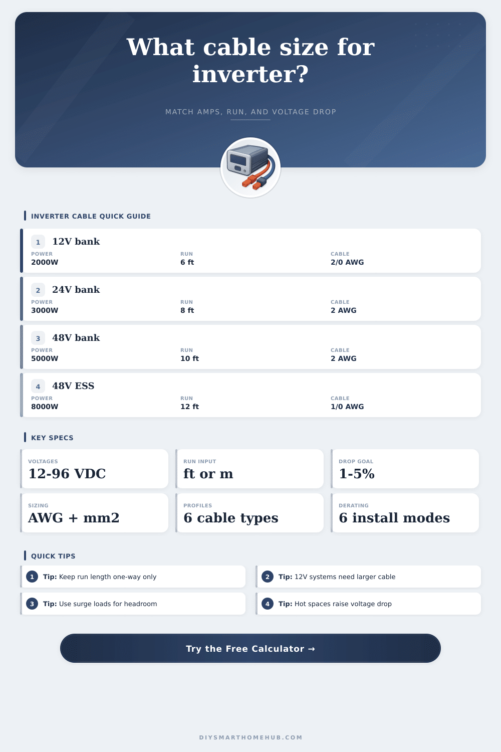
| Camper 2000W | 12 VDC | 4-6 ft | 2/0 AWG | High current forces large copper |
| Cabin 3000W | 24 VDC | 6-8 ft | 2 AWG | Voltage doubles and amps drop |
| Backup 5000W | 48 VDC | 8-10 ft | 2 AWG | Lower current keeps drop manageable |
| ESS 8000W | 48 VDC | 10-12 ft | 1/0 AWG | Surge headroom needs more ampacity |
Battery-to-inverter cables are sized from the DC side current. A 12 V inverter carrying the same watts needs about four times the current of a 48 V system.
The current travels out and back, so a 6 ft one-way placement becomes 12 ft of conductor in the voltage drop math. Keeping the inverter close to the battery bank helps fast.
An inverter may stop functioning during a power surge. An inverter may also stop functioning if the cable between the battery bank and the inverter are too small for the inverter. If the cables are too small for the inverter, the cables will overheat, and they will cause a drop in the voltage delivered to the inverter.
Furthermore, an undersized cable will create a brownout or a fire hazard for the inverter. To avoid these problem, the size of the cable must be selected correct. To determine the correct size of the cable, an understanding of the relationship between current, distance, and heat is require.
How to choose the right cable for your inverter
The inverter require a significantly high amount of mathematics to determine how many amp the inverter will require to provide the right amount of watts to power the inverters system. Inverters pull amps from the battery and convert them to watts to power the inverter. These amps create heat in every foot of wire.
Additionally, if the voltage is increased, such as changing from a 12-volt battery bank to a 24-volt battery bank, the inverter will halve the amps required. For instance, to power a 2000-watt inverter with a 12-volt battery bank will require 180 amps of continuous operation. However, to power the same 2000-watt inverter with a 48-volt battery bank will require less then 50 amps of continuous operation.
Systems with a low voltage will require a thicker cable to reduce the resistance from the cable so that power is not wasted as heat. Otherwise, the inverter will not receive the voltage it require to perform it’s function. Another factor to consider is the voltage drop in the system.
The current will leave the battery, enter the inverter, and then exit the inverter and return to the battery. Thus, the current passes through each wire twice. A voltage drop of a few percent could prevent the inverter from providing power to the appliance connected to it.
Many appliances will create a power spike that will be between two and three times the wattage that the appliance normaly use. Thus, if the inverter cables are not sized to handle this power spike, the inverters cable will fail. The materials used to construct the cables will also impact the performance of the inverter.
Copper is preferred because it has a low resistance in the wire. Depending on the inverter, different type of copper cables are used. Fine-strand welding cable is used in areas where flexibility is important to avoid cracking the cable in tight space.
For damp areas, tinned marine cable will withstand the dampness of the area. Aluminum is a cheaper material than copper; however, its resistance is higher. To compensate for the higher resistance, a thicker gauge of aluminum cable is required.
Additionally, to prevent fire hazard, the lugs used on the aluminum cables must be appropriate for aluminum with antioxidant paste on the contact. The area where the cables will be installed will also impact their performance. For instance, if the inverter cables are placed in a conduit or within the hot engine bay of the vehicle, the cables will shed heat poor.
In these areas, the ampacity that the cables can produce will drop by 15 to 25 percent. Cables placed in open air will breath better and allow more power to the inverter. People often make a mistake in estimating the size of the inverter cable instead of calculating it.
If the size is estimated, it can lead to the inverter shutting down due to a low battery alarm. If the voltage drops too low from the load on the inverter, it will shut off. Furthermore, heat derating of the cables must be considered when purchasing inverter cable.
The ampacity tables for the inverter cables assume the air will be cool. However, if the batteries is warm or the inverter is in a warm space, the resistance in the wire will increase. If the cables are bundled together or located in a warm room, the ampacity of the cables will have to be derated to 80 or 90 percent of the rated amperage of the cable.
To account for this, cable ampacity calculator are available to calculate the ampacity of the cables after the temperature derating is accounted for. To ensure the best performance of the inverter, the inverter should be placed as close to the battery as possible. The shorter the cable between the battery and the inverter, the less voltage will be dropped, and the less money will be spent on the cables.
Using separate positive and negative cables is better than using the chassis of the vehicle as the return cable for the inverter. Moreover, the lug on the inverter should be torqued to the proper amount for the size of the cable, and the connection should be inspected once a year to ensure heat cycles on the lug have not loosened the connection. By ensuring that the size of the cable is chosen to allow the cables to handle the worst case scenario of power surge, the inverter will function smoothly without any flickering or shutting down of the inverter.