Thermocouple Resistance Calculator
Estimate total loop resistance, remaining run-length headroom, interface loading, and bias-current offset before you land a thermocouple on a PID, PLC, logger, or automation board.
📌Quick Presets
⚙Loop Inputs
Thermocouple Loop Results
Run the calculator to compare resistance, loading, and bias drift against your selected input hardware.
🧪Thermocouple Family Comparison
Type K
58.6 ohm per 100 ft pair. Default choice for ovens, smokers, and appliance monitoring when you need broad temperature range.
Type J
35.7 ohm per 100 ft pair. Strong output for boiler stacks, flues, and older process gear that already expects iron-constantan sensors.
Type T
29.8 ohm per 100 ft pair. Stable at low temperatures, so it is a good fit for tanks, freezers, and chilled water loops.
Type E
70.7 ohm per 100 ft pair. Highest sensitivity in this group, useful when the controller front-end is noisy or the signal is tiny.
Type N
77.6 ohm per 100 ft pair. Better stability than K at sustained heat, often chosen for kilns, heat-treat work, and furnace zones.
Type S
18.5 ohm per 100 ft pair. Noble-metal sensor for high-temperature lab or ceramic work where drift matters more than signal size.
Type R
19.0 ohm per 100 ft pair. Similar to S with slightly different alloy balance, often kept on short premium runs into stable instrumentation.
📊Reference Tables
| Type | 20 AWG /100 ft | 24 AWG /100 ft | 30 AWG /100 ft | Sensitivity | Best Fit |
|---|---|---|---|---|---|
| Type K | 58.6 ohm | 149.0 ohm | 598.4 ohm | 41 µV/°C | General heat monitoring |
| Type J | 35.7 ohm | 87.8 ohm | 355.1 ohm | 55 µV/°C | Boilers and flues |
| Type T | 29.8 ohm | 75.3 ohm | 304.3 ohm | 43 µV/°C | Cold tanks and freezers |
| Type E | 70.7 ohm | 178.0 ohm | 716.9 ohm | 68 µV/°C | Low-signal runs |
| Type N | 77.6 ohm | 197.3 ohm | 792.7 ohm | 39 µV/°C | Long hot service |
| Type S | 18.5 ohm | 46.4 ohm | 185.0 ohm | 10 µV/°C | Lab and ceramic heat |
| Type R | 19.0 ohm | 47.8 ohm | 191.0 ohm | 10 µV/°C | Glass and premium probes |
Resistance values above are pair resistance for a one-way run length of 100 ft, based on OMEGA resistance-per-double-foot tables at 20 °C. Type N uses 1.324 × Type K resistance.
| AWG | Type K /100 ft | 100 ohm Max Run | Typical Fit |
|---|---|---|---|
| 14 AWG | 14.6 ohm | 684 ft | Long plant runs |
| 16 AWG | 23.0 ohm | 435 ft | Shared cable trays |
| 18 AWG | 37.4 ohm | 267 ft | Mid-length panel runs |
| 20 AWG | 58.6 ohm | 171 ft | Typical DIY control loop |
| 24 AWG | 149.0 ohm | 67 ft | Short appliance harness |
| 26 AWG | 238.1 ohm | 42 ft | Compact probe pigtails |
| 30 AWG | 598.4 ohm | 17 ft | Bench-level sensor leads |
| 36 AWG | 2408.0 ohm | 4 ft | Very short bead probes |
Max-run figures use the 100 ohm guideline at 20 °C with no extra connector resistance. Hot environments and multiple terminals reduce that headroom.
| Input Class | Impedance | Loss @ 25 ohm | Loss @ 50 ohm | Loss @ 100 ohm | Where It Fits |
|---|---|---|---|---|---|
| Low-Z ADC | 100 kΩ | 0.025% | 0.050% | 0.100% | Simple microcontroller front-ends |
| Bench Meter | 200 kΩ | 0.012% | 0.025% | 0.050% | Portable test gear |
| Kiln PID | 500 kΩ | 0.005% | 0.010% | 0.020% | Standalone temperature control |
| PLC mV Card | 1 MΩ | 0.003% | 0.005% | 0.010% | Panel automation |
| DIN Transmitter | 5 MΩ | 0.001% | 0.001% | 0.002% | Remote 4-20 mA head-end |
| High-Z Logger | 10 MΩ | 0.000% | 0.001% | 0.001% | DAQ and trend logging |
Voltage-divider loading is usually tiny on quality thermocouple inputs, but it still matters when a thin run lands on a lower impedance analog front-end.
| Project Preset | Type / Gauge | Run | Estimated Loop | Reference Note |
|---|---|---|---|---|
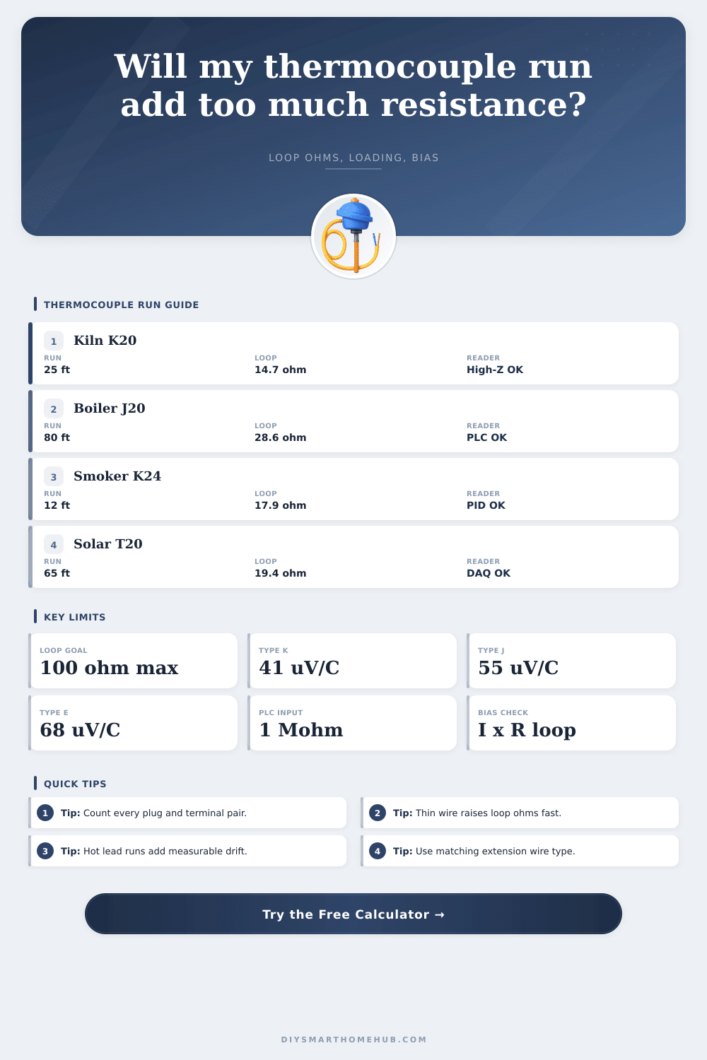
| Kiln Shelf Controller | K / 20 AWG | 25 ft | 14.7 ohm | Comfortable headroom for a PID or logger |
| Smart Smoker Probe | K / 24 AWG | 12 ft | 17.9 ohm | Thin braided lead stays reasonable at short distance |
| Hydronic Boiler Stack | J / 20 AWG | 80 ft | 28.6 ohm | PLC cards usually tolerate this easily |
| Sauna High-Limit | N / 20 AWG | 35 ft | 27.2 ohm | Higher heat stability with moderate loop loss |
| Solar Tank Sensor | T / 20 AWG | 65 ft | 19.4 ohm | Low-temp liquid monitoring benefits from T |
| Engine EGT Logger | K / 24 AWG | 18 ft | 26.8 ohm | Watch connector count around the firewall |
Tip: When you compare gauges, keep the thermocouple type fixed first. Switching from 24 AWG to 20 AWG usually buys more headroom than swapping inputs on the controller.
Tip: Count every detachable plug, terminal block, and transition head. Each pair adds a little resistance and another place for oxidation to shift the reading over time.
Thermocouples is sensors that measure the temperature within a given environment by creating small amount of voltage based off the difference in heat at the thermocouple junction. When thermocouples are use, they create a millivolt signal that the resistance within the wires that connects the thermocouple to the controller can, however, alter. If the resistance within those wires are too high, the controller that measure the voltage will recieve an inaccurate reading from the thermocouple.
As a result, the voltage drop that occur due to high resistance within the thermocouple wires can make the temperature that the controller reads appear more different than the actual temperature of the environment. The resistance within the wires can be determined by a variety of different factor. One of the most important factor related to the resistance within the wires is the gauge of the wire itself.
How Wire Resistance Affects Thermocouple Readings
The gauge of the wire indicates the thickness of the wire. For instance, 14 AWG wire is thicker than 24 AWG wire, meaning that 14 AWG wire will have a lower resistance than 24 AWG wire. For these reason, if thin wires (like 24 AWG wire) is used over long distance, the resistance within those wires will be high.
High resistance within the wires will lead to error in the thermocouple temperature readings due to the voltage drop that occurs across the resistance within those wires. In addition to the gauge of the wires, another factor that can impact the resistance within the wires is the temperature within the environment. The resistance within a wire increase as the temperature of that wire increases.
Thus, if the wires are locate in a hot area within the environment, such as near a boiler, the resistance within those wires will be higher than if the wires are locate in a cool portion of that environment. Thus, heat within the environment will increase the resistance within the wires, leading to more error in those temperature measurements. Additionally, the number of connector and plugs along the thermocouple circuit will also increase the resistance within the circuit.
Each connector contain some degree of resistance within its material, so using many connector will increase the total resistance within the thermocouple circuit. The type of controller that measure the voltage of the thermocouple will also impact how resistance within the wires impact the accuracy of those temperature measurements. Some controller have high level of input impedance.
High levels of input impedance mean that the resistance within the thermocouple wires will not affect the controller much. Other controllers have low level of input impedance. Low levels of input impedance mean that the resistance within the thermocouple wires will affect the controller.
Thus, for example, if a controller with low levels of input impedance is use, it will be necessary to use thick wires in the thermocouple to minimize the error in the temperature measurements. There are also different type of thermocouples. For instance, type K thermocouples is some of the most common types of thermocouples and are use in a variety of heat related applications.
Type J thermocouples are often use to measure the temperatures of flue gases. Type T thermocouples are use to measure cold temperatures, and type S and type R thermocouples are use to measure extremely high temperatures. Each type of thermocouple has specific characteristic and requirement regarding the wiring of those thermocouples.
For instance, type K thermocouples have specific resistance characteristic based upon the gauge of wire use in creating those thermocouples. Similarly, type J thermocouples have specific characteristic based upon the gauge of wire use in creating those thermocouples. Each type of thermocouple must be matched to its intended use, as well as the extension wire use with that thermocouple.
If the type of thermocouple does not match the extension wire, error will be created at the junction between the thermocouple and the extension wire. Thus, it is important to ensure that the thermocouple and extension wire match each other in type. In order to ensure that the thermocouple provide accurate temperature measurements of the environment in which it is deployed, there are a few rules that should of be follow when installing the thermocouples.
First, if the distance between the thermocouple and the controller is to be long, it is important to utilize thicker wire (of higher gauge) to minimize the resistance within the wire. Second, the number of connectors and other plug along the thermocouple should be minimize. Each plug along the thermocouple will introduce some degree of resistance into the circuit.
Third, the temperature of the environment in which the thermocouple is utilize should be considered. High temperatures will increase the resistance within the wires of the thermocouple. Finally, extension wires that are utilize with the thermocouple should be matched to the alloy of the thermocouple.
Any other type of mismatches between the thermocouple and extension wire can lead to the creation of ghost voltage. By managing the resistance within the thermocouple loop, the thermocouple will provide accurate measurement of the temperature of the environment being measure, and the controller will provide accurate measurement of the temperature of that environment.