Radiant Floor Tubing Calculator
Estimate tubing footage, loop count, average loop length, water volume, design flow, and rough heat output for hydronic radiant floors. Switch units, pick a room shape, subtract blocked areas, and compare spacing and floor finish before laying out your manifold.
Preset Zones
Preset scenarios fill the form with realistic radiant floor layouts and automatically run the calculator so you can compare loop plans quickly.
Layout Inputs
The calculator uses heated floor area, tubing spacing, tube size, tail lengths to the manifold, floor finish transfer factor, water temperature, and design delta T to build a practical loop plan.
Calculated Results
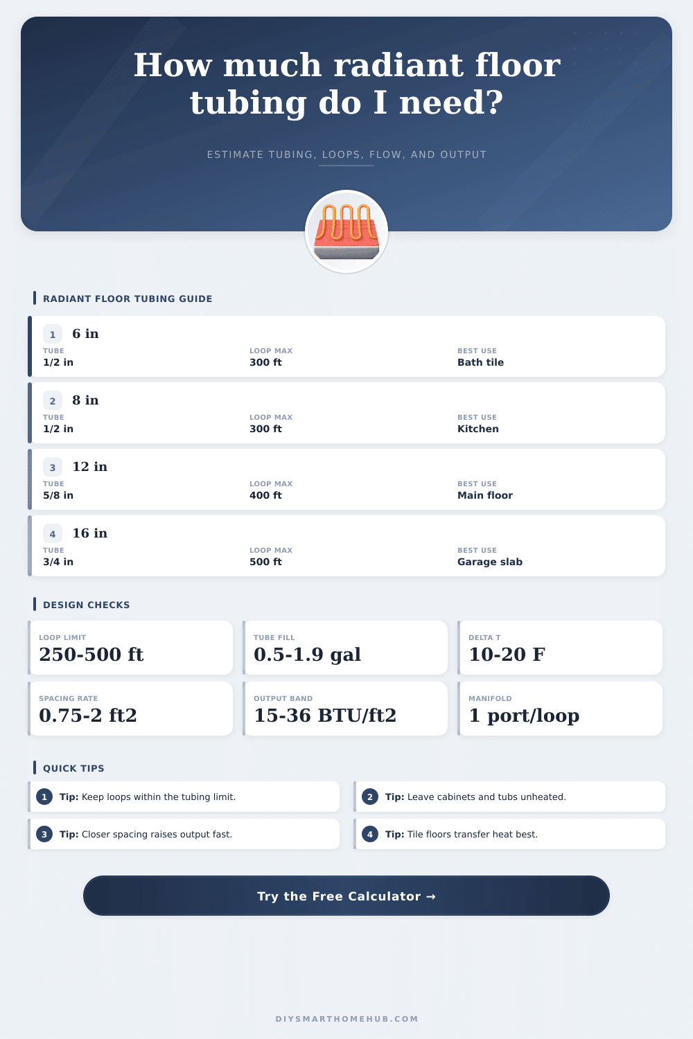
Tube Size Reference
These reference cards use conservative loop lengths that help keep pressure drop and balancing practical for typical residential hydronic radiant floor manifolds.
Spacing and Output Table
The output column below assumes tile or concrete finish and roughly 120 F average water temperature. Real delivered output shifts with finish resistance and assembly details.
| Spacing | Tubing per 100 ft2 | Approx output | Typical application |
|---|---|---|---|
| 6 in | 200 ft | 34-36 BTU/ft2 | Bathrooms, high loss perimeters, sunrooms |
| 8 in | 150 ft | 29-32 BTU/ft2 | Kitchens, entry zones, plate systems |
| 9 in | 133 ft | 26-29 BTU/ft2 | Main living areas with good insulation |
| 12 in | 100 ft | 21-24 BTU/ft2 | Basements, bedrooms, general slab heat |
| 16 in | 75 ft | 15-18 BTU/ft2 | Low load garages and large utility slabs |
Quick rule: linear feet per square foot equals 12 divided by spacing in inches. That is why tighter spacing improves output but raises tubing footage and loop count.
Floor Finish Comparison
Finish resistance changes how easily heat leaves the tubing assembly and reaches the room. These factors are used by the calculator for the rough output estimate.
| Finish | Transfer factor | Typical output impact | Notes |
|---|---|---|---|
| Tile or stone | 1.00 | Best baseline | Fast transfer and even surface temperatures when spacing is tight. |
| Polished concrete | 1.03 | Slightly above baseline | Good for slab systems because the slab itself becomes the emitter. |
| Luxury vinyl | 0.90 | Moderate reduction | Check manufacturer limits for surface temperature and maximum water temperature. |
| Engineered wood | 0.86 | Moderate reduction | Stable engineered products generally work better than solid wide planks. |
| Laminate | 0.84 | Moderate reduction | Use assembly ratings that are approved for radiant heat floors. |
| Carpet and pad | 0.68 | Large reduction | High resistance often pushes you toward tighter spacing or warmer water. |
Common Project Benchmarks
These sample layouts show how spacing and tube size change the manifold plan. Use them as a quick sanity check against your own result.
| Project | Heated area | Spacing | Typical tubing |
|---|---|---|---|
| Hall bath tile | 45 ft2 | 6 in | 100-120 ft total |
| Primary bath | 110 ft2 | 6-8 in | 210-260 ft total |
| Kitchen retrofit | 180 ft2 | 8 in | 300-360 ft total |
| Bedroom zone | 160-180 ft2 | 9-12 in | 190-250 ft total |
| Basement slab | 450-500 ft2 | 12 in | 520-650 ft total |
| Garage slab | 600 ft2 | 12-16 in | 600-780 ft total |
| Open plan first floor | 700-800 ft2 | 9 in | 1050-1300 ft total |
| Whole house manifold | 1800 ft2 | 9-12 in | 2100-2600 ft total |
Layout Notes
Try to keep average loop lengths reasonably close to each other. A zone with one very short loop and one very long loop is harder to balance and often needs more adjustment at the manifold.
Fixed cabinets, shower pans, tubs, islands, and built-in storage usually stay outside the heated pattern. Excluding them reduces over-ordering and keeps the tubing plan more realistic.
Radiant floor heating you can install in many ways. You commonly lay radiant tubes in, on or under the floor. Between popular methods are installations for upper floor, suspended concrete slab, sleeper, floor beam and slab on grade.
In concrete slab on grade, you bind radiant PEX-tubes to the reinforcing mesh or rebar by means of wire ties, before pour the concrete. It works well to also clamp the PEX-tubes to styrofoam insulation.
Ways to Install Radiant Floor Heating
PEX-tubes with oxygen barrier are used for floor heating, melting of ice and snow, and for baseboard or radiator heating. You use them for supply and return lines to boilers and fan coils. Warm PEX has oxygen barrier, lasts at least 200°F working temperature against 180°F maximum, and allow longer rolls.
Never lay any connection in pour concrete slab. PEX-tubes easily twist around obstacles and corners, so you can effect complex arrangements for best warming. It resists scale, chlorine and corrosion, what extends the life and trust.
After you counted the whole tube length, comes the time to set the number of sections or loops. For 1/2″ tubes standard is 300 feet in section. However the Radiant Panel Association advises of 250 until 350 feet.
It Is possible to share the floor in 300-foot bits, so 150 feet for supply, 150 for return, meandering them up of subfloor in 12 inches of interval.
Compact 4’ x 2’ Warm-Sheet radiant floor panels are easily stockable and installable. They give permanent insulation. AquaHeat, done in North Carolina, bid big flexibility and fit variants for particular needs.
Available also complete kits with tubes, manifolds and design of the arrangement. Some systems use copper with short loops, usually under 200 feet, what improves efficiency and level floor temperatures. Plastic and rubber systems require supply and return manifolds, but copper only return.