⚡ Power Factor Calculator
Calculate power factor, apparent power (kVA), reactive power (kVAR), and phase angle from your electrical system values
| Phase Angle (°) | Power Factor (cos θ) | kVAR per kW | Efficiency Category |
|---|---|---|---|
| 0° | 1.000 | 0.000 | Unity — Ideal |
| 5° | 0.996 | 0.087 | Excellent |
| 10° | 0.985 | 0.176 | Excellent |
| 15° | 0.966 | 0.268 | Very Good |
| 18.2° | 0.950 | 0.329 | Very Good (target min) |
| 25.8° | 0.900 | 0.484 | Good |
| 31.8° | 0.850 | 0.620 | Acceptable (utility min) |
| 36.9° | 0.800 | 0.750 | Below Standard |
| 45.6° | 0.700 | 1.020 | Poor |
| 53.1° | 0.600 | 1.333 | Very Poor |
| Real Power | Existing PF | Target PF 0.95 | Target PF 1.00 |
|---|---|---|---|
| 10 kW | 0.70 | 6.6 kVAR | 10.2 kVAR |
| 10 kW | 0.80 | 3.7 kVAR | 7.5 kVAR |
| 10 kW | 0.85 | 2.1 kVAR | 6.2 kVAR |
| 50 kW | 0.70 | 33.0 kVAR | 51.0 kVAR |
| 50 kW | 0.80 | 18.6 kVAR | 37.5 kVAR |
| 100 kW | 0.75 | 56.3 kVAR | 88.2 kVAR |
| 100 kW | 0.85 | 20.7 kVAR | 61.9 kVAR |
| 100 kW | 0.90 | 8.7 kVAR | 48.4 kVAR |
| Real Power (kW) | PF | Single Phase kVA | Three Phase kVA |
|---|---|---|---|
| 5 kW | 0.80 | 6.25 kVA | 6.25 kVA |
| 10 kW | 0.85 | 11.76 kVA | 11.76 kVA |
| 25 kW | 0.90 | 27.78 kVA | 27.78 kVA |
| 50 kW | 0.92 | 54.35 kVA | 54.35 kVA |
| 100 kW | 0.95 | 105.26 kVA | 105.26 kVA |
| 200 kW | 0.85 | 235.29 kVA | 235.29 kVA |
| Formula | Find | Given | Equation |
|---|---|---|---|
| Power Factor | PF | kW, kVA | PF = kW ÷ kVA |
| Apparent Power | kVA | kW, PF | kVA = kW ÷ PF |
| Reactive Power | kVAR | kVA, kW | kVAR = √(kVA² − kW²) |
| Phase Angle | θ (°) | PF | θ = arccos(PF) |
| Real Power (3Φ) | kW | V, I, PF | kW = V × I × √3 × PF / 1000 |
| Real Power (1Φ) | kW | V, I, PF | kW = V × I × PF / 1000 |
| Correction kVAR | kVAR needed | kW, PF1, PF2 | kVAR = kW × (tanθ1 − tanθ2) |
| Efficiency | % loading | kW, kVA | % = (kW / kVA) × 100 |
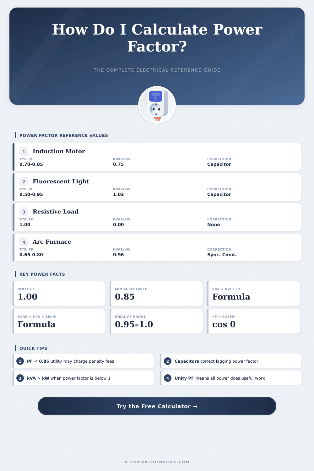
Power factor simply shows how well one uses the electricity. It matches the ratio between real and apparent power. The real power one measures in kilowatts (kW), while the apparent in kilovolt-amperes (kVA).
The math is easy: power factor is kW divided by kVA. Devices draw power from the power grid, but only part of it truly gets used and does useful work. The power factor shows how big that usable part is.
What Is Power Factor and How to Fix It
The power factor ranges between 0 and 1. Value near 1 means better efficiency. Generally good power factor sits between 1.0 and 0.95.
Between 0.95 and 0.85 one considers it average. Under 0.85 it is bad. Typical commercial buildings commonly have values between 0.98 and 0.92.
In circuits with alternating electricity, power factor matches the cosine of the phase angle between voltage and current. Ideally, the phase difference between voltage and current would be zero. In real life though there almost always exists a bit of differnece between them.
The equation for power in AC comes from P equals V multiplied by I multiplied by power factor. In circuits with direct electricity or only resistive, the power factor always is 1.0.
What causes low power factor? Inductive loads, like engines, and capacitive loads are the main causes. Engines shift the current out of phase with the voltage.
From that view, power factor is simply the removal of phase, that motor loads cause in the system. Low power factor shows, that the energy source is less efficient based on the kind of load, that it meets.
To fix bad power factor, one can add capacitors in the circuits. Because a capacitor is the electrical opposite of an inductor like an engine, it helps too compensate the phase shift. If a company uses heavy engines to cut or grind, engineers will install banks of capacitors to balance those big inductive loads.
But simply adding a capacitive set to the main line is not wise. When inductive devices turn off, the power factor can drop negatively, which is dangerous. Better is to add capacitors to separate engines, so that they turn on together with them.
Another option is to install automatic power factor corrector, that connects and disconnects capacitance to keep it around 0.95 to 0.97.
Most home devices and those with engines already have built-in power factor corrector. It improves the efficiency and reduces the heat. In United States, it is required for energy star rating.
Those small devices, sold as energy savers, usually carry only small capacitive amount, that almost does not help for real correction of power factor.
Industrial clients with bad power factor can receive extra bills from the supplier. Reactive power itself does not get lost as heat. It simply gets stored and returned to the circuit source.
However the real costs of power, that causes the handling of that reactive need, are real expenses. So one controls power factor in high-load places. It affects how much current must be delivered, howmuch heat builds up and also the billing costs.