⚡ Transformer Fault Current Calculator
Calculate short-circuit fault current, symmetrical fault level, and protection coordination data for any transformer
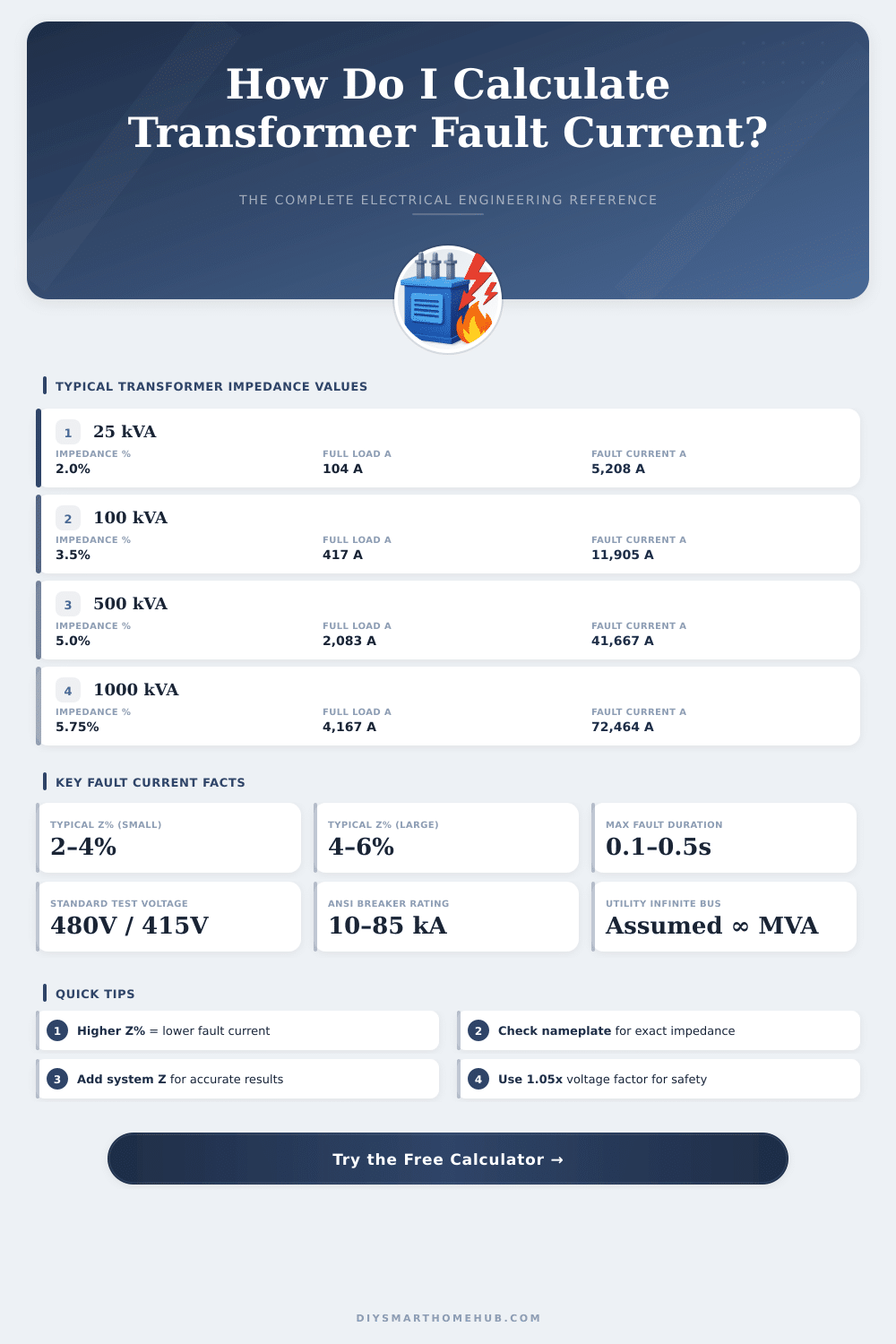
| kVA Rating | Z% (typical) | Full Load Amps | Sym. Fault Current (kA) | Asymm. Fault ×1.6 (kA) |
|---|---|---|---|---|
| 15 kVA | 2.0% | 18 A | 0.90 kA | 1.44 kA |
| 25 kVA | 2.0% | 30 A | 1.50 kA | 2.40 kA |
| 45 kVA | 2.5% | 54 A | 2.16 kA | 3.46 kA |
| 75 kVA | 3.5% | 90 A | 2.57 kA | 4.12 kA |
| 100 kVA | 3.5% | 120 A | 3.43 kA | 5.49 kA |
| 167 kVA | 4.0% | 201 A | 5.02 kA | 8.04 kA |
| 250 kVA | 5.0% | 301 A | 6.02 kA | 9.63 kA |
| 500 kVA | 5.0% | 601 A | 12.03 kA | 19.25 kA |
| 750 kVA | 5.5% | 902 A | 16.40 kA | 26.24 kA |
| 1000 kVA | 5.75% | 1,203 A | 20.92 kA | 33.47 kA |
| 1500 kVA | 5.75% | 1,804 A | 31.38 kA | 50.20 kA |
| 2000 kVA | 5.75% | 2,406 A | 41.84 kA | 66.94 kA |
| 2500 kVA | 5.75% | 3,007 A | 52.30 kA | 83.67 kA |
| kVA | 208V FLA | 240V FLA | 480V FLA | 4160V FLA | 13.8 kV FLA |
|---|---|---|---|---|---|
| 25 | 69 A | 60 A | 30 A | 3.5 A | 1.05 A |
| 50 | 139 A | 120 A | 60 A | 6.9 A | 2.09 A |
| 100 | 278 A | 241 A | 120 A | 13.9 A | 4.18 A |
| 250 | 694 A | 601 A | 301 A | 34.7 A | 10.46 A |
| 500 | 1,388 A | 1,203 A | 601 A | 69.4 A | 20.93 A |
| 1000 | 2,776 A | 2,406 A | 1,203 A | 138.8 A | 41.85 A |
| Device Type | Voltage Class | Standard AIC Rating | High AIC Rating | Typical Application |
|---|---|---|---|---|
| Residential MCB | 120/240V | 10 kA | 22 kA | Homes, small panels |
| Commercial MCCB | 480V | 18 kA | 65 kA | Commercial buildings |
| Industrial MCCB | 480V | 35 kA | 100 kA | Industrial panels |
| Low Voltage PCB | 480/600V | 65 kA | 200 kA | Main switchboards |
| Current Limiting Fuse | 600V | 200 kA | 300 kA | High fault scenarios |
| MV Vacuum CB | 4.16–15 kV | 25 kA | 40 kA | Substations |
| Formula | Description | Variables |
|---|---|---|
| Isc = (kVA × 1000) / (√3 × V × Z%) | 3ϕ Symmetrical Fault | kVA=rating, V=secondary V, Z=per unit |
| Isc = (kVA × 1000) / (V × Z%) | 1ϕ Symmetrical Fault | kVA=rating, V=secondary V, Z=per unit |
| IFLA = (kVA × 1000) / (√3 × V) | 3ϕ Full Load Amps | kVA=rating, V=line-to-line voltage |
| Iasym = Isym × 1.6 | Asymmetrical Peak (X/R=6) | Multiply sym by 1.6 factor |
| Ztotal = Zxfmr + Zsystem | Total Impedance | Add transformer + source impedance |
| MVAsc = kVA / (Z% / 100) | Fault MVA Level | kVA=rating, Z=percentage |
Transformer fault electricity is considered one of the main calculations in electrical engineering. It helps to estimate how many electricity could run during short circuit at the secondary part of the Transformer. Precise calculation of that value matters a lot for choosing the right protection and control the cost of devices.
The main equation however stays fairly easy. Fault electricity matches to the full load current divided by the impedance percentage. To find the full load in amps, one shares the VA rating of the Transformer by the line voltage that one multiplies by 1,732.
How to Calculate Transformer Fault Current
For instance, for 1000-kVA Transformer rated at 480 volt, the full load current result from 1 000 000 divided by 831,36, what gives around 1202,84 amps.
Impedance has here a key part. A Transformer with lower impedance will provide stronger fault electricity. The ratio between fault and rated electricity drops, when the Transformer owns higher impedacne percentage.
For usual standard Transformers in general uses, the fault electricity should not pass 25 times the rated electricity. Basically, the size of fault electricity depends on the impedance of the Transformer.
There is a mode called the Infinite Bus Method. It delivers a simple mode to estimate the biggest fault electricity, that a Transformer fits to give during a fault. This approach assumes, that the Transformer binds to a perfect voltage source with zero upstream impedance.
In study of short circuit, the main limiting element ultimately comes from the impedance of the Transformer itself and its kVA rating.
Protection devices must have the right size. Their breaking skills usually should pass by 20 to 25 percent the planned fault electricity. Those extra safety margins consider possible changes in the installation, tolerances of measurements and some future changes of the system.
Use online computers, that allow to enter the kVA of the Transformer, the secondary voltage and the impedance percentage, to quickly sea the possible fault electricity. Some programs specially estimate the level of short circuit fault electricity for three-phase core-type Transformer with D/Yn-wound connection. Others deal with impedance calculations for machines at the end of circuit, that feeds the secondary winding of Transformer.
Ground fault electricity forms another side, that one must estimate too. It relates to the electricity, that passes through the soil, when a fault in the winding of Transformer cause, that the electricity takes an unplanned way through the ground instead of the usual circuit. During calculation of ground fault electricity, one deals with zero sequence electricity instead of the standard short circuit rating.
When one has the possible short circuit electricity at the bus of the system, one must convert it in equal impedance of thesystem together with that of the Transformer. Later, the calculations of faults depend on the kind of fault and the connection of the Transformer, because that affects the net of zero sequence.