⚡ Frequency to Voltage Converter Calculator
Convert input frequency (Hz) to output voltage using real F/V converter formulas — LM2907, LM331, and custom scale factors
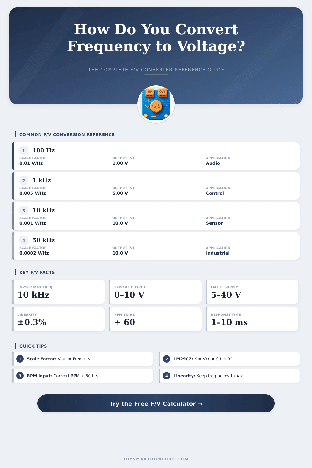
| Input Frequency | Scale Factor K (V/Hz) | Output Voltage (0–5V span) | Output Voltage (0–10V span) |
|---|---|---|---|
| 100 Hz full scale | 0.0500 V/Hz | 5.00 V at 100 Hz | 10.00 V at 100 Hz |
| 500 Hz full scale | 0.0100 V/Hz | 5.00 V at 500 Hz | 10.00 V at 500 Hz |
| 1,000 Hz full scale | 0.0050 V/Hz | 5.00 V at 1 kHz | 10.00 V at 1 kHz |
| 5,000 Hz full scale | 0.0010 V/Hz | 5.00 V at 5 kHz | 10.00 V at 5 kHz |
| 10,000 Hz full scale | 0.0005 V/Hz | 5.00 V at 10 kHz | 10.00 V at 10 kHz |
| 100,000 Hz full scale | 0.0000500 V/Hz | 5.00 V at 100 kHz | 10.00 V at 100 kHz |
| RPM | Hz (1 pulse/rev) | Hz (2 pulses/rev) | Hz (4 pulses/rev) |
|---|---|---|---|
| 60 RPM | 1.00 Hz | 2.00 Hz | 4.00 Hz |
| 300 RPM | 5.00 Hz | 10.00 Hz | 20.00 Hz |
| 600 RPM | 10.00 Hz | 20.00 Hz | 40.00 Hz |
| 1,000 RPM | 16.67 Hz | 33.33 Hz | 66.67 Hz |
| 1,500 RPM | 25.00 Hz | 50.00 Hz | 100.00 Hz |
| 3,000 RPM | 50.00 Hz | 100.00 Hz | 200.00 Hz |
| 6,000 RPM | 100.00 Hz | 200.00 Hz | 400.00 Hz |
| 10,000 RPM | 166.67 Hz | 333.33 Hz | 666.67 Hz |
| Application | Typical Freq Range | Output Voltage | Recommended IC |
|---|---|---|---|
| Automotive Tachometer | 0–200 Hz | 0–5 V | LM2907 |
| Motor Speed Control | 0–1,000 Hz | 0–10 V | LM2907 / LM331 |
| Flow Meter Sensor | 1–5,000 Hz | 0–5 V | LM331 |
| PLC Analog Input | 0–10,000 Hz | 0–10 V | LM331 |
| Vibration Monitoring | 10–10,000 Hz | 0–5 V | AD650 |
| Audio Processing | 20–20,000 Hz | 0–5 V | AD650 / VFC32 |
| Industrial Encoder | 0–100,000 Hz | 0–10 V | VFC32 |
| Ultrasonic Sensor | 20,000–200,000 Hz | 0–5 V | AD650 |
Vout = Vcc × fin × C1 × R1
where C1 is in Farads and R1 is in Ohms. Keep fin below fmax = 1 / (2 × C1 × R1) for linearity.
Vout = (fin × Rs × Ct × 2.09) / 0.001
Typical linearity is ±0.01% making it ideal for precision measurement applications up to 100 kHz.
Hz = (RPM / 60) × Pulses_per_Revolution
A 4-cylinder engine with 2 pulses/rev at 3000 RPM gives 100 Hz input signal.
K (V/Hz) = Vout_max / Freq_max
Then: Vout = K × fin + Voffset
This applies to all IC types and custom op-amp based designs.
In the core, conversion of frequency to voltage does a task very basic: it receives incoming signals or driving waves in various frequencies and converts them in full electrical output, of average voltage of electricity. What makes these tools useful is their talent to handle all kinds of signals, from low frequencies to those of high, with good loyalty. The charm of such builds lies in that the output voltage grows in step with the enclosed frequency, what opens many options for usage in practice.
When one reaches the building of such stuff, there are some basic options for parts. The 555 timer probably stays the most traditional choice, it receives an input frequency signal and gives output proportionate voltage. Later comes the LM331 that works according to the same idea: the input frequency directly converts into output voltage.
How to Convert Frequency to Voltage
Also the LM2917 commonly used, especially in automotive systems. For sample, one can take the RPM-signal from the motor and help by means of the LM2917 turn it into voltage, that Arduino truly can read, so that one builds digital RPM-measure on screen. In such cable, one lays resistance, capacitor and diode on the signal way; they simply remove any DC-level, that could stay around.
Even so, one not always needs whole circuits. Basic high-pass RC-filter tied too a detector works surprisingly well as simple converter. By means of changing the values of parts, one reaches quite good linear response.
Extra mode is use a monostable multivibrator, that runs itself one time for every input pulse and gives pulse of permanent beam always. Notable is the method with integration and rectifier, where bigger frequencies give less output voltage; rather to that, what one usually wants. The different aspect is differentiator followed by rectifier: if the input frequency grows, the output voltage follows, what commonly is the wanted result.
Such converters shine in mechanical systems, where one always watches repeated events. It also well served for conversion of analog to digital and for cases, when one must combine signals during longer periods. The single-chip models, those built on one chip; are surprisingly easy and cheap, making the shift between analog waves and digital driving without big trouble.
In summary, there are two main kinds: designs based on multivibrator and those with balance of loop. Some older fixes, as circuit around the 741 operational amplifier working as relaxation oscillator, well answer if one only cares about low energy and low frequencies.
Correct details are more important, than one thinks. The input signal must stay stable at least during half of a second or more. The output electricity usually reaches 5 mA, and one works with DC-source between 12 and 30 volts.
Multi-turn potentiometer allows to calibrate the conversion of frequency to voltage. Here the limit: the most available parts reach max about 1 MHz, so searching something, that handles 100 MHz, is truly hard. The majority of available parts have input frequency in the tens of kilocycles.
The linearity can be a real problem… I met cases, where tripling the frequency gave only double of voltage, but adding resistance inseries before the capacitor settled that perfectly.