🧲 Ampere Turns (MMF) Calculator
Calculate magnetomotive force for coils, solenoids, relays, transformers & electromagnets
| Turns (N) | 0.1 A | 0.5 A | 1 A | 2 A | 5 A | 10 A |
|---|---|---|---|---|---|---|
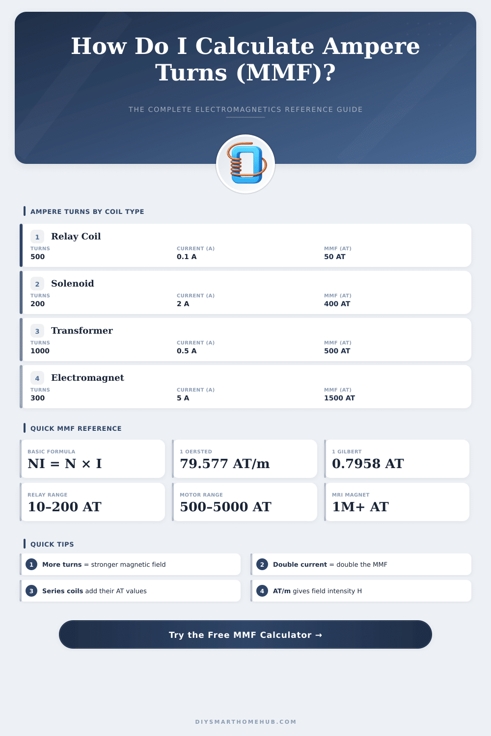
| 50 | 5 AT | 25 AT | 50 AT | 100 AT | 250 AT | 500 AT |
| 100 | 10 AT | 50 AT | 100 AT | 200 AT | 500 AT | 1,000 AT |
| 200 | 20 AT | 100 AT | 200 AT | 400 AT | 1,000 AT | 2,000 AT |
| 500 | 50 AT | 250 AT | 500 AT | 1,000 AT | 2,500 AT | 5,000 AT |
| 1,000 | 100 AT | 500 AT | 1,000 AT | 2,000 AT | 5,000 AT | 10,000 AT |
| 2,000 | 200 AT | 1,000 AT | 2,000 AT | 4,000 AT | 10,000 AT | 20,000 AT |
| 5,000 | 500 AT | 2,500 AT | 5,000 AT | 10,000 AT | 25,000 AT | 50,000 AT |
| MMF (AT) | L = 0.05 m | L = 0.1 m | L = 0.2 m | L = 0.5 m | L = 1 m |
|---|---|---|---|---|---|
| 100 AT | 2,000 A/m | 1,000 A/m | 500 A/m | 200 A/m | 100 A/m |
| 500 AT | 10,000 A/m | 5,000 A/m | 2,500 A/m | 1,000 A/m | 500 A/m |
| 1,000 AT | 20,000 A/m | 10,000 A/m | 5,000 A/m | 2,000 A/m | 1,000 A/m |
| 5,000 AT | 100,000 A/m | 50,000 A/m | 25,000 A/m | 10,000 A/m | 5,000 A/m |
| 10,000 AT | 200,000 A/m | 100,000 A/m | 50,000 A/m | 20,000 A/m | 10,000 A/m |
| Quantity | SI Unit | CGS Unit | Conversion Factor | Notes |
|---|---|---|---|---|
| MMF | Ampere-turn (AT) | Gilbert (Gb) | 1 AT = 1.2566 Gb | F = NI |
| Field Intensity | A/m | Oersted (Oe) | 1 Oe = 79.577 A/m | H = F / L |
| Magnetic Flux | Weber (Wb) | Maxwell (Mx) | 1 Wb = 108 Mx | Φ = B x A |
| Flux Density | Tesla (T) | Gauss (G) | 1 T = 10,000 G | B = μ0 μr H |
| Reluctance | A/Wb (H⁻¹) | Gb/Mx | 1 A/Wb = 1.257×10⁻¸ Gb/Mx | R = L / (μA) |
Ampere-turns may seem scary at the start, but really the idea itself is nice and simple. They measure the magnetomotive force… Or MMF, if you like the short form.
That belongs to the MKS-system (metre-kilo-second) and has the symbol At. At its base it shows what happens when one ampere of steady current passes through a single loop of wire.
What Are Ampere-Turns?
If someone mentions turns of wire, that talks about the number of times that electrical wire itself wraps to create an electromagnetic coil. So ampere-turns simply describe two things that matter: the number of turns that you have, and the size of current through them.
How does one count ampere-turns? Very easily. One multiplies the current in amperes by the number of turns.
Here it is, I times N. Assume that you have 2 amperes flowing through a coil with 100 turns. So you get 200 ampere-turns. The same you could reach with 10 turns and 20 amperes instead.
The thcikness of the wire or the width of the coil? None of those matters. One ampere through one turn always gives one ampere-turn.
Here is the key point: a bigger number of wire turns or stronger current makes your magnetic field more powerful. Really, ampere-turns serve mainly to measure the magnetomotive force. It does create the magnetic flow in a magnetic circuit, and ampere-turns give a practical weigh for that measure.
Now things get more interesting when you link coils together. If you link two coils side by side to a steady current source, the MMF stays the same as one single coil would produce. Each gets only half of the current.
And if you connect the same two coils in series with that same current source? The magnetomotive force doubles. Because now double the number of turns gets the whole current.
Because of that, for solenoids there is a formula link between magnetic field strength and ampere-turns. It simply works like this: B equals µNI divided by L. Here N is the number of turns, I the current, L the length of the solenoid, and µ the magnetic permeability of the core material. The part NI, that is your ampere-turn value.
Here electromagnets get tricky, even so. Adding more turns means adding more wire length. More wire causes more resistance.
More resistance slows the current. So building electromagnets must be careful balancing. Ampere-turns matter also for relay switches.
The AT-rating shows how much magnetic field strength the switch needs to activate. A high AT-value shows that the relay switch is tough. It needs a stronger magnet before itwill work.
So, ampere-turns and webers are not the same. Ampere-turns measure the MMF, while webers measure the magnetic flow. Think about MMF as about voltage in an electrical circuit, it is the driving force that causes magnetism.