Arc Fault Current Calculator
Estimate available bolted fault current, likely arcing-current range, conductor drop, and whether the selected protection pickup sits inside a practical clearing window.
📌Arc fault presets
⚙Fault current inputs
This calculator estimates current magnitude and protective-device pickup fit. It does not calculate incident energy, approach boundaries, or PPE.
Arc current worksheet
Enter inputs and calculate.
🔧Conductor and protection spec grid
About 2.525 ohms per 1000 ft at reference temperature.
Detection depends on waveform, current level, duration, and device design.
Planner band for comparing low and high arc estimates to protection.
Use qualified review for field work, code decisions, and equipment labels.
📊Arc current factor table
| Arc condition | Typical gap | Voltage effect | Current fraction use |
|---|---|---|---|
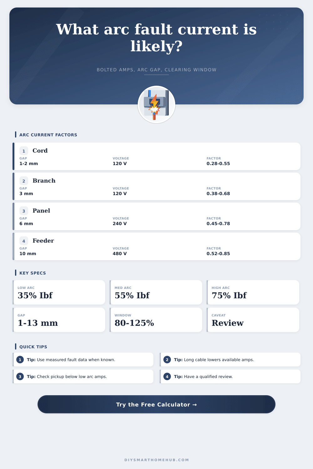
| Series arc in cord or device lead | 1-2 mm | Load current dominates | Usually capped by connected load current. |
| Parallel branch arc in outlet box | 2-5 mm | 120 V may be intermittent at wider gaps | About 0.35-0.70 of bolted current for planning. |
| Panel or feeder enclosure | 6-13 mm | 240 V to 480 V sustains gaps better | About 0.45-0.85 of bolted current depending on enclosure. |
| DC string or battery circuit | 3-20 mm | DC zero crossing is absent | Use DC factor and verify listed device interruption rating. |
🔌Conductor resistance reference
| Conductor | Ohms per 1000 ft | Common branch use | Fault-current effect |
|---|---|---|---|
| 14 AWG copper | 2.525 | 15 A lighting or receptacle branch | Long runs can sharply reduce available arcing current. |
| 12 AWG copper | 1.588 | 20 A receptacle branch | Lower resistance keeps more bolted current available. |
| 10 AWG copper | 0.999 | 30 A equipment circuit | Often above magnetic bands when source is strong. |
| 6 AWG copper | 0.395 | Feeder, EV, or subpanel circuit | Source impedance often dominates over conductor length. |
| 1 AWG aluminum | 0.253 | Larger feeder | Useful where long feeders still need high clearing current. |
⏱Protection clearing table
| Protection type | Typical current window | Clearing expectation | Planner note |
|---|---|---|---|
| 15 A AFCI breaker | Arc detection plus 5-10x magnetic region | Tens of ms when detection criteria are met | Listed AFCI response is waveform-dependent, not only amps. |
| Thermal magnetic breaker | Magnetic pickup often 5-10x rating | Fast at high fault current, slower below pickup | May not clear low-current series arcing by magnetic action. |
| Current-limiting fuse | Strong response above fuse curve threshold | Very fast at high multiples of rating | Compare against the published time-current curve. |
| DC fuse or breaker | Must be DC rated for voltage and fault level | Depends on DC device curve | Verify interrupt rating and polarity limits before field use. |
🏠Common arc fault scenarios
| Scenario | Input pattern | Expected current behavior | What to check |
|---|---|---|---|
| Damaged extension cord | 120 V, small gap, series or parallel | Series current may sit near load current | AFCI detection, cord listing, and breaker rating. |
| Loose receptacle termination | Long branch, small device box | Heating and arcing can occur below magnetic pickup | Connection integrity and AFCI coverage. |
| Feeder lug fault | Higher voltage, larger conductor, enclosure | Arc current can remain a large share of bolted current | Breaker curve, SCCR, and equipment review. |
| PV or battery DC arc | DC source, open air, wider gap | Can sustain without AC zero crossing | Listed DC protection and disconnect ratings. |
💡Practical tips
When you think about an electrical arc, your mind might conjure up some dramatic burst of electricity that blows all the breakers in the home. Movies portray them like that… But real life isn’t quite so Hollywood, nor nearly so exciting. An arc doesn’t always go out with a bang. Many is sustained at low amperage which gradually heats wire conductors until insulation gives way or heat builds to the point where something nearby catches fire. Normal overcurrent protection frequently fails to detect this type of event. If an attached load only pulls 12 amps through a series arc, that won’t trip a breaker rated for 15.
That’s why folks misunderstands what makes up risk. They think higher current = bad; lower current is fine. Not true. Lower current for long periods can do just as much harm.
Why Low Current Arcs Are Dangerous
Before we get into that though, you should know that there’s a difference between arcing current and bolted fault current. Bolted fault current assumes that a wire touches a metal box directly with zero resistance. This gives us a theoretical max. It lets us use it as a baseline for selecting equipment, but it has no information on how the actual arc will behave. Because the plasma channel between conductors creates huge amounts of impedance, arcing current is always less.
That’s where the above calculator comes in… It takes into account your particular voltage and gap size, and estimates how much this reduces amount flowing. And remember, a long conduit run and/or a high source impedance shrink the amount of bolted current that is available before it even gets to the point of fault. Maybe you’re protected for fifty-thousand amps, while all that can realy flow is five-thousand. It all depends on the size of arc gap.
The size of the arc gap changes everything; a tiny one millimeter gap in a damaged cord holds current much better than a wider separation inside a panel. The latter is going to carry current a lot betterer. Arcs usually extinguish rapidly when the AC waveform reaches zero in open air, but they can sustains higher currents for longer periods inside an enclosure that traps ionized gas and heat. That lets the arc reignite readily at each cycle. The arc behavior from a feeder lug failure is quite different than a desk cord arc. One is load-limited and temporary, while the other can be source-limited and destructive. Where does the fault occur matters. This difference make all the difference in protection strategy.
Thermal magnetic breakers work either through heating from excessive current or through magnetic attraction from a high current. Neither are particularly good at responding to low level arcing below the point where they will trip. These are arc-fault circuit interrupters. These devices looks for the distinctive electrical signal of an arc independent of how much current is flowing. But AFCIs also only go so far. Current has to be above the device’s response window and long enough for it to register. The fault is invisible if the arcing current is below the working response curve of whatever protective device you are using. Check to see that your calculated low end arc current is above the protective device’s effective response curve.
And then there’s conductor length: That also matters, surprisingly. Resistance grows as you add more of the same size wire (which is why an aluminum house wiring job may be better in some respects than copper), and a long run of small-gauge wire will cut fault current by enough to keep things safe… except that it won’t trip most breakers, so you’re relying instead on arc protection from equipment and conductors to clear before they melt down, which takes longer then the breaker tripping time. This explains why a 15-amp circuit running down a hundred feet may leave you vulnerable to slow-burning arcs that never trigger a breaker compared to one right next to the panel.
The page has a table of numbers for all this stuff. You plug in the wire size to see how each factor affects the results. This shows you what to expect regarding whether your hardware can detect the fault, let alone clear it.
So what? Arc current estimation doesn’t have to be an academic exercise. If you know how much arc current there might be, it helps you determine whether additional protection is needed, or if your present scheme has holes. Basically, you’re creating a map of the conditions before trouble, fire, failure of any kind (occurs). And by considering voltage, impedance, and gap size together, it’s not “code compliance,” but rather real-world risk management. Whatever protection you employ must respond when response is required.
Most of us build systems around idealized best-case scenarios with clean component failures. Electricity however, doesn’t give two hoots about our preference. Electricity will seek the path of least resistance. Electricity keeps trying to keep itself flowing. Whether or not your system is capable of detecting and clearing these lower level but sustained faults is what separates a house fire from a nuisance trip. The math lets you understand the risk without having to experience it as smoke.