Battery Short Circuit Current Calculator
Estimate prospective short circuit current from battery voltage, string resistance, BMS resistance, cable loop resistance, parallel strings, peak factor, and fuse interrupting rating.
Calculation breakdown
| Chemistry | Nominal cell voltage | Common full voltage | Typical cell IR range | Fault behavior |
|---|---|---|---|---|
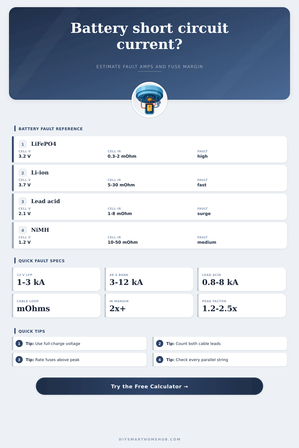
| LiFePO4 | 3.2 V | 3.45 to 3.65 V | 0.3 to 2 mOhm for large prismatic cells | Low resistance, high steady fault current, moderate peak multiplier. |
| Lithium-ion NMC/NCA | 3.6 to 3.7 V | 4.1 to 4.2 V | 5 to 30 mOhm for many cylindrical cells | Fast peak current; BMS and nickel strip resistance often dominate small packs. |
| Lead acid / AGM | 2.0 V | 2.12 to 2.15 V | 1 to 8 mOhm per 2 V cell equivalent | Very strong surge current when fully charged, especially near the terminals. |
| NiMH | 1.2 V | 1.4 to 1.45 V | 10 to 50 mOhm for common cells | Lower voltage per cell but resistance still matters in series strings. |
| Cable size | Ohms per 1000 ft at 20 °C | Round-trip mOhm per ft | Fault-current effect |
|---|---|---|---|
| 12 AWG | 1.588 | 3.176 | Small batteries can become cable-limited quickly. |
| 8 AWG | 0.6282 | 1.256 | Useful for medium DC loads with short fault paths. |
| 2 AWG | 0.1563 | 0.313 | High fault current remains likely near the battery. |
| 4/0 AWG | 0.0490 | 0.098 | Cable adds little resistance in short inverter leads. |
| Margin result | Meaning | Calculator basis | Action cue |
|---|---|---|---|
| Below 1.0x | Interrupting rating is below estimated peak fault current. | Fuse IR A / peak fault A | Use a device with a higher DC interrupting rating. |
| 1.0x to 1.99x | Rating clears the estimate, but margin is thin. | Peak multiplier and resistance assumptions drive this result. | Recheck battery IR, cable length, and worst-case voltage. |
| 2.0x to 4.99x | Healthy engineering margin for many home DC systems. | Prospective peak remains well under device rating. | Confirm the fuse is rated for the actual DC voltage. |
| 5.0x or more | Large interrupting headroom. | Peak fault is far below the entered rating. | Other limits may become cable ampacity or BMS coordination. |
| Preset | Series / parallel | Typical loop resistance | Expected result |
|---|---|---|---|
| 12 V LiFePO4 pack | 4S1P | Low battery IR plus short 4 AWG leads | Often lands in the low kiloamp range. |
| 48 V home battery | 16S2P | Parallel strings reduce cell stack resistance | Peak current can exceed small DC fuse ratings. |
| 12 V AGM battery | 6 lead-acid cells | Very low source resistance near terminals | Short-circuit current can be several kiloamps. |
| UPS battery tray | 24S1P | More series cells, moderate lead length | Higher voltage pushes serious prospective current. |
Use the shortest credible fault path for interrupting checks. A fault at the battery terminals usually produces more current than a fault at the far end of a cable run.
Do not count on a BMS current limit unless the device documentation explicitly says it is a certified short-circuit current limiter for the DC voltage involved.
The potential for short circuit current indicates how serious a fault might be: minor nuisance vs. Catastrophic fire. Knowing this number will give you an idea of what kind of energy would flow during a resistive drop nearly down to zero. That’s far different from a normal operating level of power, it means the danger of system failure.
The common presumption is that your typical fuse can handle whatever comes along which is foolish unless you’ve got some idea just how much current we are talking about. Stored chemical energy get converted to heat immediately when there’s a short circuit so make sure you’re calculating right. Using your own system specs, this calculator will output those numbers for you.
How to Calculate Short Circuit Current for Safety
First, enter the voltage your system was running when the short occured (not the nominal average). So if your fully-charged battery is thirteen point eight volts, you’ll input 13.8 into the calc. Because safety devices is designed for the worst case scenario, you’re going to assume it’s worse than that. You want a comfortable margin between that peak surge and your device rating.
Next, consider the impedance of each battery chem. For instance, LiFePO4 cells can dumps big loads instantly with little-to-no forewarning. This leads to low impedance and high-current capabilities. Lead-acid batteries do offer a heck of a spike in current but drop off over time due to their heating up. Knowing what you’ve got affect your plan of protection.
How it works: More parallel = more current, more parallel = less total resistance. For example, if you have two identically sized banks in parallel, you’d double your capacity with half the resistance inside battery bank. That lower resistance means greater risk of bigger fault currents at the main busbar which is why you don’t want to look at just one cell datasheet for the risk. Enter several strings into the tool and numbers will reflect what you’re using out there. Model the real set-up and get more accurate numbers.
The equation factors in cable size and length that adds resistance between the equipment and the battery. The thicker the wire, the greater the power capacity but the lower the resistance to a short circuit. Longer runs to panels from inverters add naturaly resistance of a longer loop. But it does nothing for faults that are at the battery terminals.
Design for the weakest link: Where’s the most likely spot for a fault? Heat also impacts how well things work. Copper becomes more resistant as it warms, this means it will draw less than its peak current which is good. However, it also warns you that there is stress on those cables.
What Fuse? Theoretical calculations must be matched against practical constraints. For instance, a fuse might have a 50 amp continuous load rating but a 3,000 amp interrupting rating, that’s how much current the fuse is designed to safely handle when it trips on a surge. If the fuse isn’t up to the challenge then instead of cleanly breaking, it’ll probably just explode. Then you’ll have molten metal and shrapnel tearing into your enclosure.
Keep some breathing room between whatever you calculate the maximum surge to be and the fuse rating. Two times or more is plenty. This is because you must also consider the age of components and unknown variables in calculations. To check the values you put in, the table of references will give you the range of resistances expected by common chemistries. You can use this as a base to see if your numbers are realistic.
Remember that things won’t be perfect in the real world. Over time, connections come loose and terminals get corroded. Including some margin for error when calculating isn’t being paranoid, it’s being an engineer. That way your system will stay safe even in less-than-ideal situations.
For safety, respect the amount of energy stored at a larger scale. Your home battery bank contains enough electricity to illuminate your whole house, and it is easy to ruin this by doing something dumb. Fear becomes preparation when you learn about fault current math, because you’re not guessing anymore, now you design with purpose. Once you know precisely how much current can flow, you will be able to create a system that will survive its own worst mistake. Now, accidentally dropping a tool is simply one more variable in an equation you should of already solved.