Furnace Flue Size Calculator
Estimate a furnace vent diameter, equivalent length, connector-rise effect, and draft warning from appliance input, vent category, height, lateral run, and elbows.
📌Furnace Venting Presets
Load a realistic starting layout, then adjust the BTU input and run dimensions to match the appliance data plate and the actual vent path.
⚙Flue Sizing Inputs
🧱Flue / Vent Material Spec Comparison
Listed double-wall gas vent for negative-pressure, non-condensing gas appliances.
Stainless special gas vent for positive pressure and higher flue gas temperature.
Plastic venting where the furnace listing and local code permit condensing exhaust.
Polypropylene vent systems are listed corrosion-resistant options for many condensing units.
📊Reference Tables
| Category | Vent pressure | Condensing | Common vent material |
|---|---|---|---|
| Category I draft hood | Negative | No | Type B vent or listed liner |
| Category I fan-assisted | Negative | No | Type B vent, sized by tables |
| Category III | Positive | No | Stainless special gas vent |
| Category IV | Positive | Yes | PVC, CPVC, PP, or listed system |
| Item | Calculator allowance | Why it matters | Check |
|---|---|---|---|
| 90 degree elbow | 5 ft equivalent | Adds flow resistance | Count each elbow |
| 45 degree elbow | 2.5 ft equivalent | Lower pressure drop | Two equal one 90 |
| Direct-vent termination | 5 ft allowance | Termination loss | Use manual value |
| Low connector rise | Draft penalty | Weakens natural lift | Flag below 2 ft |
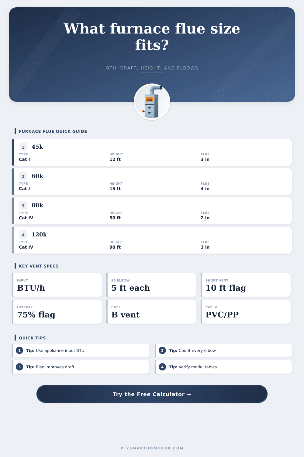
| Diameter | Cat I B vent screen | Cat IV direct vent screen | Best use |
|---|---|---|---|
| 2 in | Not typical | Up to about 60k BTU/h | Short condensing runs |
| 3 in | About 35k to 47k BTU/h | Up to about 140k BTU/h | Small furnaces or long PVC |
| 4 in | About 78k to 96k BTU/h | Up to about 220k BTU/h | Common mid-size vent |
| 5 in | About 135k to 160k BTU/h | Model-specific only | Larger Category I units |
| Layout factor | Good screen | Warning screen | Reason |
|---|---|---|---|
| Category I height | 10 ft or more | Below 10 ft | Less stack draft |
| Lateral ratio | Below 75% of height | 75% or more | Horizontal run cools gases |
| Connector rise | 2 ft or more | Below 2 ft | Less initial lift |
| Condensing run | Within model limit | Over screen limit | Pressure switch risk |
💡Venting Tip Boxes
Furnace venting are a system that allows for exhaust gas to be removed from the furnace. The furnace venting system must be sized apropiately so that the venting system dont cause problem for the furnace. A person must make sure that the furnace venting system is of the correct size for the furnace; if the furnace venting system is of the wrong size, it can either choke the furnace or allow condensation to enter the venting system.
A person should check the size of the furnace venting systems before ordering the necesary pipe for the furnace or requesting permit to pull for installation of the furnace. The size of the furnace venting system depend upon a few specific input. The inputs include the input of the appliance, the category of the vent, and the total resistance of the furnace venting system.
How to Size and Check Furnace Vents
The input of the appliance is the fuel consumption rate of the furnace that is to be vented, this isnt the amount of heat that is deliver to the house by the furnace. The category of the vent is the type of system that is used for venting the furnace, is it a negative pressure system or a positive pressure system? The total resistance of the furnace venting system is calculated from the height of the venting system, the lateral run of the venting system, and the number of elbow within the system.
Additionally, the rise of the connector to the furnace is also considered; this rise provide some lift to the exhaust gases at the furnace, which is beneficial for Category I furnaces. Category I furnaces use the “stack effect” to naturaly moving the exhaust gases out of the furnace. The strength of the draft created by the furnace is dependent upon the height of the chimney (or B vent) into which the gases is vented.
If the venting system is too short in its vertical portion, or if the lateral run of the system is too long, the draft will weaken. Weakening of the draft can lead to exhaust spillage or even incomplete combustion of the fuel gas that the furnace burns. A screening calculation can be used to determine if the draft is too weak for the Category I furnace.
Category IV condensing units are of a different design than the Category I furnaces. For Category IV condensing furnaces, the exhaust gases are “pushed” through plastic pipe to an exterior of the building. The limiting factor for these systems is the length of the pipe that is used to vent the furnace; the length of the plastic pipe should not be so longer than to prevent the furnace from igniting the fuel gas properly.
The limiting factor in these systems is the equivalent length of the plastic pipe, and the length that the pressure switch for the furnace can accept. In most actual installations of furnace venting systems, the venting system will be more significantly complex than the diagrams that is used to illustrate the concepts behind furnace venting systems. The vent may have to be routed around joists in the floor, for instance, or may have to emerge from a sidewall of the structure rather then the roof.
Any number of elbows or lengths of pipe are going to increase the total resistance of the venting system of the furnace. Each fitting must be accounted for, and each length of rise must be accounted for in the venting system. Any additional fitting or length of pipe will reduce the safety of the furnace venting system.
The material for the venting system must match the category of the venting system. Type B venting systems are used for negative pressure systems, gas appliances. Type B venting system use a double-wall construction to keep the inner pipe of the vent warm; it is important to keep the inner pipe warm for these systems.
Condensing furnaces release acidic condensate, so the venting system for condensing furnaces must be specifically list as being safe for use in environment that is acidic. The incorrect material for venting systems can lead to the furnace developing condensation issue, the condensation can lead to a leak in the venting system. There are reference tables that contains information regarding different pipe diameters, the capacity of those pipes, and the resistance created by the layout of the venting system.
These tables can assist a designer in determining whether or not the venting system of the furnace is a realistic system. However, the reference tables are not a substitute for the fuel gas code or the furnace installation instructions. Always follow the installation instruction for the furnace, as well as the fuel gas code for your area.
Most problem with furnace venting systems are caused by underestimating the total resistance of the system. A calculator can be used to test the layout of the furnace venting system prior to installing the pipe. Additionally, you should verify the diameter of the venting system and the material to be used against the specifications of the furnace to ensure the safety of the system.