DC Arc Flash Calculator
Estimate DC prospective fault current, arc voltage, incident energy, and an arc-flash boundary for batteries, PV combiner circuits, UPS buses, traction DC, and industrial DC power.
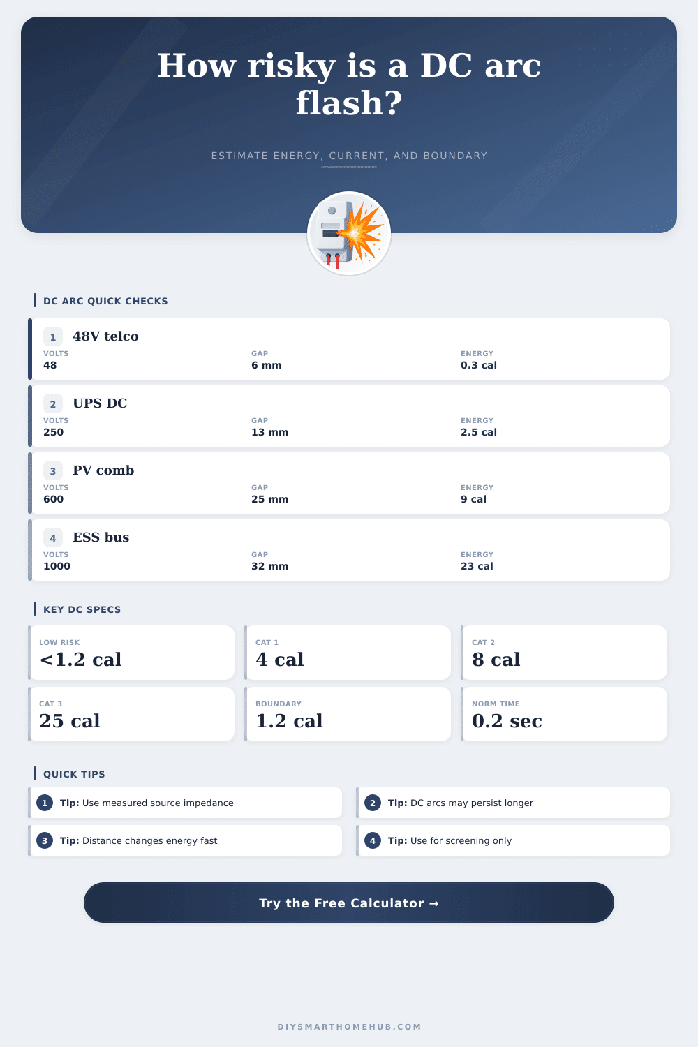
⚡Real DC Power Presets
⚙DC Arc Inputs
📊Live Input Summary
DC Arc Flash Results
Full Calculation Breakdown
🔌DC Equipment / Spec Comparison Grid
📘DC Arc Reference Tables
| DC system | Typical voltage | Typical gap | Common distance |
|---|---|---|---|
| Telecom battery plant | 48 Vdc | 6 to 13 mm | 18 in / 457 mm |
| Station battery panel | 125 Vdc | 13 mm | 18 in / 457 mm |
| UPS or DC rack bus | 250 to 380 Vdc | 13 to 25 mm | 18 to 24 in |
| PV / ESS equipment | 600 to 1500 Vdc | 25 to 32 mm | 24 to 36 in |
| Enclosure | Factor | Use when | Effect |
|---|---|---|---|
| Open air | 0.72 | PV string, open terminals | Less reflected heat |
| Disconnect box | 0.90 | Shallow small enclosure | Moderate reflection |
| Panel / combiner | 1.00 | Typical DC gear | Reference case |
| Deep bus compartment | 1.35 to 1.55 | Crowded enclosed bus | Higher incident energy |
| Energy level | Screening band | Meaning | Boundary note |
|---|---|---|---|
| Below 1.2 cal/cm² | Below arc-flash boundary threshold | Lower thermal exposure | Boundary at work distance or closer |
| 1.2 to 4 cal/cm² | Cat 1 screening range | Arc-rated PPE may be required | Boundary exceeds work distance |
| 4 to 8 cal/cm² | Cat 2 screening range | Higher energy exposure | Verify clearing and labels |
| 8 to 40+ cal/cm² | Cat 3 / Cat 4 range | Severe burn hazard | Engineering review needed |
| Clearing time | Relative energy | Protective device | DC caution |
|---|---|---|---|
| 0.02 s | 0.1x of 0.20 s | Very fast fuse / trip | Confirm current-limiting region |
| 0.10 s | 0.5x of 0.20 s | Fast DC breaker | Use arcing current, not bolted only |
| 0.20 s | 1.0x reference | Common study cap | Long DC arcs remain possible |
| 1.00 s | 5.0x of 0.20 s | Delayed or backup clearing | Usually demands mitigation review |
💡Calculation Tips
Arc flash event in DC power systems occur very quick but behave different than arc flash events in AC power systems that many electrician may encounter. Unlike AC power systems, where arcs generally lasts for a short period, DC arcs can last for a longer period once initiated. Consequently, the amount of energy released into the electrician can continue to increase after the initial fault in DC power systems.
Hence, electrician who work around battery banks, PV strings, UPS buses, and traction power systems must size the hazard before the electrician has to open an enclosure or reach across a live bus bar to access electrical equipment. To calculate the incident energy due to an arc flash fault, you must supply the voltage, the source impedance, and the clearing time of the protective device to the arc flash calculator. These three value is crucial to calculating the energy level due to an arc flash because these determine the bolted fault current, the arcing current, and the duration that the arc fault is allowed to burn.
DC Arc Flash Basics for Electricians
If any of these three parameter are changed, the outcome of the calculation will change. For instance, if the source impedance are increased, the arcing current will decrease. With a lower arcing current, the protective device will increase its clearing time since the clearing time will no longer be in an instantaneous range.
Thus, the energy levels will increase even though the short circuit current may be lower. In addition to the voltage, source impedance, and clearing time of the device, you must consider the working distance from the arc fault and the enclosure in which the equipment is installed. The working distance should follow an inverse square relationship with the arc fault since moving eighteen inches away from the arc will cut the energy exposure to the electrician in half.
However, electricians is often required to work within twenty-four inches of the arc fault. Similarly, the enclosure factor have a significant impact on the energy exposure to the electrician since a deep enclosure will reflect the heat back to the electrician. The arc flash calculator will allow an electrician to enter an enclosure factor that match the specific equipment being used.
Another factor that cause errors when screening electrical equipment for arc flash hazards is the clearing time for DC circuits. Unlike AC circuits, DC circuits will behave differently when the arcing current is less than the fault current. Hence, electricians must use the arc flash calculator and enter the clearing time for the circuit at the arcing current level instead of using the clearing time at the bolted fault current levels stated in the equipment datasheet.
By using the actual trip curve for the DC circuit breaker instead of the nameplate value, electricians may discover that the arc energy level are higher than expected that require arc-rated clothing or practices to be implemented on the job site. The parameters that you must consider when performing an arc flash study are not the same as the variables that are modeled in arc flash calculators. For instance, the internal resistance of batteries change with the temperature and the charge of the batteries.
PV strings will not deliver fault currents when it is not shining or if it is not connected to the solar array. Additionally, capacitor banks will release a high-current burst before the protective device can move to clear the fault. Although the arc flash calculator does not consider all the variable in the power system, the calculator does allow electricians to test out their assumptions about the system.
The output of the arc flash calculator is not the final number that should be noted on an electrical job site. The output of the arc flash calculator will indicate whether the incident energy is below the 1.2 calorie boundary or whether a full engineering study are needed to determine the energy of the arc fault. If the calculated energy is between eight and twenty-five calories, a verification of the clearing device is needed before any electrician work on the equipment.
The goal for the arc flash calculator is not to provide a lower number than other electricians on the job site. The goal for the arc flash calculator is to determine the source of the energy and the amount of time that the electrician has to get away from the arc fault. By understanding the energy levels and the time to get to safety, electricians will have a better understanding of the safety requirement for the electrical equipment.