Wind Turbine Gear Ratio Calculator
Match blade RPM to generator RPM using rotor diameter, wind speed, target tip speed ratio, drivetrain type, and practical stage limits for small wind turbine builds.
⚙Real drivetrain presets
📏Rotor and generator inputs
Calculation Breakdown
🧮Current drivetrain spec grid
📊Rotor TSR and gearing reference
| Rotor style | Common TSR band | Gear ratio behavior | Planning cue |
|---|---|---|---|
| Savonius drag rotor | 0.8 to 1.5 | Often needs a large step-up ratio | Useful for demonstrations and low-speed charging experiments. |
| Multi-blade pump rotor | 1 to 3 | Low rotor RPM with strong shaft torque | Split ratios if driving a faster permanent magnet generator. |
| Darrieus vertical-axis | 3 to 5 | Moderate gearing for compact generators | Check startup torque before choosing a high generator RPM. |
| Three-blade HAWT | 6 to 8 | Commonly lands in 2:1 to 5:1 step-up range | Good match for belt, chain, or small gear stages. |
| Two-blade fast HAWT | 7 to 10 | May need less step-up at the same diameter | Watch tip speed and acoustic limits as RPM rises. |
⚒Drivetrain stage comparison
| Drive type | Typical single-stage ratio | Efficiency used | Best fit in this calculator |
|---|---|---|---|
| Timing belt | 1.5:1 to 4:1 | 96% per stage | Quiet micro turbines and clean small-generator layouts. |
| V-belt | 1.5:1 to 5:1 | 93% per stage | Flexible pulley spacing where some slip is acceptable. |
| Roller chain | 1.5:1 to 4:1 | 95% per stage | Rugged low-speed rotors with higher torque transfer. |
| Spur gears | 2:1 to 6:1 | 97% per stage | Compact enclosed gearboxes with fixed alignment. |
| Planetary gears | 3:1 to 6:1 | 94% per stage | High step-up density when bearing loads are managed. |
📐Common turbine gearing examples
| Project scale | Rotor and wind anchor | Generator target | Typical ratio outcome |
|---|---|---|---|
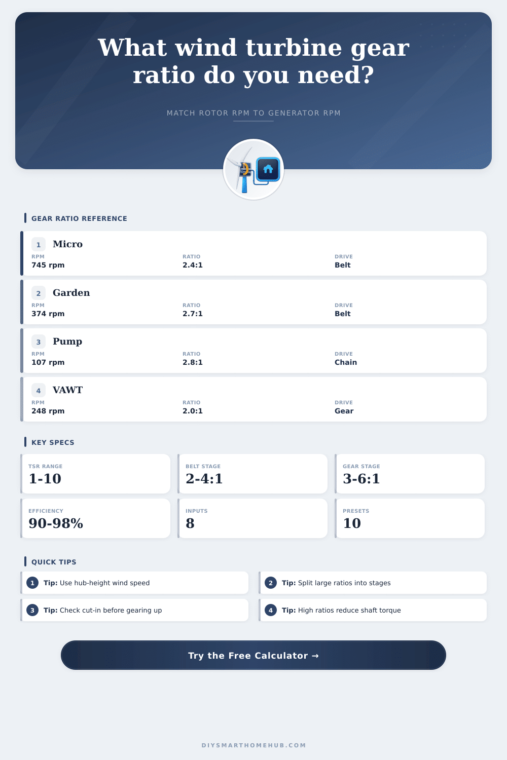
| Micro PMA charger | 1.0 m rotor at 6 m/s and TSR 6.5 | 1,800 rpm | About 2.4:1 step-up with a belt stage. |
| Garden 48V turbine | 2.4 m rotor at 6.7 m/s and TSR 7 | 1,000 rpm | About 2.7:1 step-up for a compact PM generator. |
| Water pump rotor | 5.0 m multi-blade rotor at 7 m/s and TSR 2 | 300 rpm | About 2.8:1 step-up while keeping rotor torque useful. |
| Darrieus yard VAWT | 2.0 m rotor at 6.5 m/s and TSR 4 | 500 rpm | About 2.0:1 step-up with gear or chain drive. |
| Automotive alternator test | 2.0 m rotor at 7 m/s and TSR 6 | 2,200 rpm | High ratio; usually needs multiple stages or a lower-RPM generator. |
⚡Generator RPM target bands
| Generator type | Useful RPM target | Gear ratio pressure | Calculator note |
|---|---|---|---|
| Low-speed permanent magnet alternator | 150 to 600 rpm | Low | Often works direct drive or with a small step-up ratio. |
| Small PM generator | 600 to 1,200 rpm | Moderate | Common match for 2:1 to 4:1 wind turbine drivetrains. |
| Converted induction motor | 1,000 to 1,800 rpm | High | Requires a fast rotor, a large ratio, or both. |
| Automotive alternator | 1,800 to 3,000 rpm | Very high | Use the result as a warning flag for small rotors. |
✅Gear ratio calculation tips
A gear ratio is another important component for small wind turbines because the gear ratio will determine whether the wind turbine will effectively charge the battery or remain idle. The rotor will turn at a speed determined by the wind and the blades of the rotor, but most generators require higher RPMs than what the rotor will turn at. If the wind turbine does not have an means of achieving such a high gear ratio, then the designer will either under-load the rotor or over stress the generator.
By entering the diameters of the rotor, the wind speed, the tip speed ratio and the target generator speed, the calculator can determine the necessary gear ratio for the system, as well as the division of that gear ratio into various stages of that system. The tip speed ratio is another important piece of information for the designer because it will determine the speed at which the blades will turn. A higher ratio will indicate that the blades are narrow and the rotor will turn at a higher rate.
Choosing Gear Ratios for Small Wind Turbines
High ratios are generally desirable for efficiency at steady winds. However, high ratios also cause the tips of the blades to move at high speeds that can cause noise and stress on the rotor components. Lower tip speed ratios is used for rotors with a wider diameter or drag-based rotors.
These will be harder to start rotating at low wind speeds, but they will produce more power per square meter of the area of the rotor. By selecting the tip speed ratio for the system, the calculator will determine the RPM of the rotor, as well as the gear ratio necessary to connect the rotor to the generator. Due to the fact that most designers tend to use a single gear ratio, small problems may result.
For instance, single 6-to-1 pulley systems lose some of the wrap of the belt, place additional load on the bearings of the system, and have a tendency to slip if there are strong gusts of the wind. One method of avoiding these problems is to split the gear ratio of the system across two or three stages. This will ensure that each of the pulleys in the system maintains a comfortable size and does not fail in operation.
The number of stages will be the smallest number that maintains a gear ratio that is within the limits for each of the stages. These limits can be adjusted for different types of timing belts, chains, and spur gears. Gear ratios that are too high for any of these components will reduce the efficiency of those components.
Each additional stage of gearing will reduce the efficiency of the system. For instance, timing belts that may have 96% efficiency will lose some of that power through three stages of gearing. This loss of power will reduce the available torque to turn the generator.
This information can be used to size the generator, as well as to determine if the given diameter for the rotor will provide enough torque to overcome the resistance of the generator at the cut-in speed of the generator. If the ratio of torque of the rotor compared to the torque of the generator is too low, the rotor will not be able to begin to turn the generator against its resistance. The type of rotor that will be used for the wind turbine has a specific range for its tip speed ratios.
For three-blade horizontal axis rotors the tip speed ratios will generally be between 6 and 8. Two-blade fast rotors will have tip speed ratios of approximately 10. However, vertical axis and water pump rotors will have lower tip speed ratios.
By selecting the type of rotor that is to be used, the tip speed ratio can be loaded into the system. This will show a range of tip speed ratios that are applicable for the selected type of rotor. If the tip speed ratio that is chosen is outside of this range, then the system is experimental in nature and may require additional considerations to be built in the system.
The type of generator that will be used will also impact the gear ratio of the system. For low-speed permanent magnet generators, both direct drive and gear drive systems can be used. However, other types of generators, like converted induction motors or automotive alternators will require higher RPMs.
These can either be achieved through a fast rotating rotor or through gearing stages. In the calculator, both options can be considered. In both instances, the RPM that should be entered is the RPM at which the generator begins to effectively produce charge from the wind, not the maximum RPM of the generator.
The wind speed that will be used in the system is another important piece of information. Small changes in the speed of the wind will have great effects upon the downstream components of the wind turbine. Wind speeds at the generator will be higher than those at ground level.
Furthermore, the indicated wind speed that should be used is not the maximum wind speed that will exist in the area. Instead, the speed that is chosen can be tested at various speeds to determine if a variable gear ratio system is needed. Another consideration that should be made in the design is the mechanical losses of the system.
For instance, belts will stretch over time and gears will wear. High gear ratios will cause the system to experience these losses at a higher rate. Furthermore, the high ratio will generate heat that will require more frequent lubrication of the system.
Low ratios, on the other hand, will reduce the generation of heat. However, the rotor will not reach the efficient RPM of the generator. The design of the system does not replace the calculations of these components, but will provide a starting point for those calculations.
Once all of the components have been selected, the parts of the system will need to be sized according to the load that will be placed upon them due to the gear ratio of the system. For instance, larger pulleys will reduce the tension of the belt, which can be helpful in high load situations. Planetary gear stages allow for high gear ratios in small areas of the system, but require complex alignments.
The efficiency number that can be provided by the calculators accounts for the type of drive that is to be used in the system. Thus, the tool can compare the efficiency of different types of drives before beginning to construct the system. A correctly geared machine will reach the cut-in of the generator at a lower wind speed, as well as operate over a wider range of wind speeds.
Furthermore, it will not cycle as quickly from overspeed to underspeed, which shortens the life of the generator. Thus, the numbers that are provided by the calculator can be used to align the components of the system, the wind, the rotor, and the generator. When these three components are correctly aligned, the system will have a better chance of functioning as intended.