WiFi Antenna Length Calculator
Calculate physical antenna element length from frequency, antenna geometry, velocity factor, trim allowance, and start-long tuning margin.
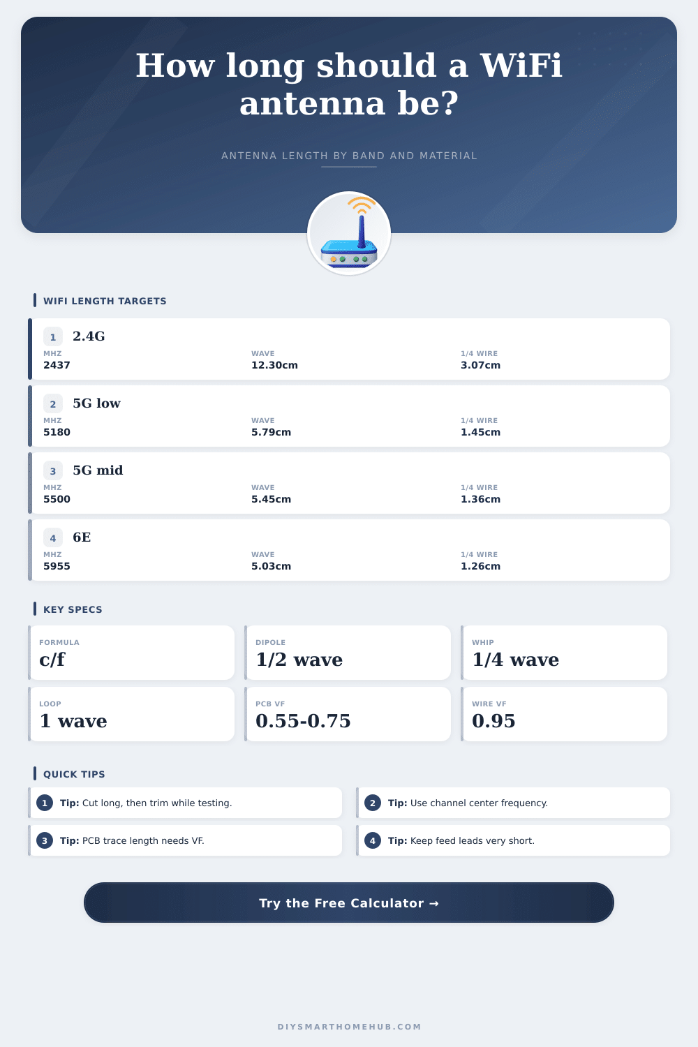
Antenna Length Results
| Band / channel | Center MHz | Free-space wavelength | Quarter-wave wire, VF 0.95 |
|---|---|---|---|
| 2.4 GHz channel 1 | 2412 | 4.89 in / 12.43 cm | 1.16 in / 2.95 cm |
| 2.4 GHz channel 6 | 2437 | 4.84 in / 12.30 cm | 1.15 in / 2.92 cm |
| 2.4 GHz channel 11 | 2462 | 4.80 in / 12.18 cm | 1.14 in / 2.89 cm |
| 5 GHz channel 36 | 5180 | 2.28 in / 5.79 cm | 0.54 in / 1.38 cm |
| 5 GHz channel 100 | 5500 | 2.15 in / 5.45 cm | 0.51 in / 1.29 cm |
| 5 GHz channel 165 | 5825 | 2.03 in / 5.15 cm | 0.48 in / 1.22 cm |
| 6 GHz channel 1 | 5955 | 1.98 in / 5.03 cm | 0.47 in / 1.19 cm |
| 6 GHz channel 233 | 7115 | 1.66 in / 4.21 cm | 0.39 in / 1.00 cm |
| Geometry | Main result | Electrical fraction | Best use |
|---|---|---|---|
| Quarter-wave monopole | One vertical element | 0.25 wave | Router whip, IoT node, test jig |
| Half-wave dipole | Each leg length | 0.25 wave per leg | Balanced indoor antenna |
| 5/8-wave vertical | Long radiator | 0.625 wave | Experimental vertical with matching |
| Full-wave loop | Total loop circumference | 1.00 wave | Compact loop or square test antenna |
| Coaxial sleeve dipole | Radiator and sleeve | 0.25 wave each | Simple coax-fed vertical dipole |
| PCB inverted-F starter | Loaded trace length | 0.25 wave adjusted | Module antenna layout estimate |
| Material or structure | Typical VF | Length effect | Use in calculator |
|---|---|---|---|
| Bare copper wire in air | 0.98 | Nearly free-space length | Wire prototypes |
| Insulated hookup wire | 0.95 | Slightly shorter | Most quick builds |
| Rubber duck internal helix | 0.90 | Shortened starter only | Replacement whip estimates |
| Open PCB trace over ground | 0.78 | Board dielectric slows wave | Printed trace estimate |
| RG-58 polyethylene coax | 0.66 | Much shorter section | Sleeves and coax stubs |
| FR4 microstrip estimate | 0.58 | Strong dielectric shortening | Controlled PCB layouts |
| Project scenario | Band | Antenna target | Starting note |
|---|---|---|---|
| ESP32 room sensor | 2.4 GHz ch 6 | PCB inverted-F | Use board VF, tune near enclosure |
| Garage camera bridge | 5 GHz ch 36 | Half-wave dipole | Keep both legs symmetrical |
| Router test whip | 2.4 GHz ch 1 | Quarter-wave monopole | Add 3 or 4 quarter-wave radials |
| Outdoor yard AP | 5 GHz ch 100 | 5/8-wave vertical | Needs matching network or coil |
| Coax sleeve experiment | 2.4 GHz ch 11 | Sleeve dipole | Sleeve and radiator are similar length |
| 6E bench prototype | 6 GHz ch 1 | Quarter-wave wire | Small errors matter more at 6 GHz |
The length of a WiFi antenna are a critical factor in the performance of the antenna. The length of a WiFi antenna will determine how well the antenna can transmit and recieve a signal. If the length of the antenna isnt correct, then the WiFi antenna will have a decreased range in the WiFi signal and the connection to the WiFi antenna will experience instability.
The length of a WiFi antenna must be sized specific for the frequency of the WiFi signal and the material of the antenna itself. Many individuals attempt to determine the length of the antenna by utilizing the information that is published on various antenna forums or the datasheets of the antennas themselves. However, these datasheets does not always account for the material that will be used to construct the antenna.
How to Find the Right Length for a WiFi Antenna
For instance, the antenna may incorporate insulation that will slow the movement of the WiFi signal, it may incorporate ground planes on circuit boards, or the antenna may be constructed of plastic material. Each of these factors will impact the length of the antenna; loading will shorten the length of the antenna that is required for the antenna to function proper. Thus, if these factors are ignored in the design of the antenna, the antenna may end up being electrically too long.
An electrically too long antenna will exhibit a high Standing Wave Ratio (SWR) and will not perform as well as it could potential. In order to determine the length of the WiFi antenna, the rate of the free-space wavelength can be used. The free-space wavelength can be calculated by dividing the speed of light by the frequency of the WiFi signal.
The length of the antenna can be calculated by applying a fraction to this initial calculation. For example, if the antenna is to be constructed as a whip antenna, the antenna will need to be a quarter of the free-space wavelength. Furthermore, when using this calculation, it is also important to account for the velocity factor of the conductor that the user will utilize to construct the antenna.
This factor determine the rate at which the signal will travel through that specific material. Additionally, it is also important to include a trim allowance to the length of the calculated antenna. In using an antenna length calculator, it is important to enter the parameters of the antenna build that will be constructed.
For instance, it is important to use the channel center frequency of the WiFi signal as the user input for frequency. The channel center frequency will be the most commonly utilize frequency within the WiFi channel. Additionally, it is important to select the correct geometry for the antenna; a whip antenna will have a different geometry than a dipole antenna.
Furthermore, it is also important to ensure that the velocity factor is correctly entered into the antenna calculator. For instance, a bare wire will have a velocity factor of close to one, but a wire with insulation will have a different velocity factor than the bare wire; the velocity factor will impact the length of the antenna that is required to be construct. In cutting the antenna, it is important to start with a length that is longer than the calculated length.
Starting the antenna with a length that is shorter than the calculated length will prevent any ability to lengthen the antenna once it has been cut; a shorter antenna cannot be lengthened. However, starting the antenna with a length that is longer than the calculated length allows for the antenna to be trimmed to the appropriate length. Furthermore, the radials setting on the antenna length calculator will allow for scaling of the quarter-wave length of the antenna if the user plans to include ground plane wires to the antenna build.
The antenna will experience changes to its calculated performance due to the environment in which it will be deployed. For instance, if the antenna is to be constructed with an ESP32 sensor, the plastic case that contains the sensor will change the resonance of the antenna. Furthermore, if the antenna is constructed as a coax sleeve dipole antenna, the mounting hardware that is used to mount the antenna may alter the resonance of the antenna.
Thus, the antenna length can only be confirmed once it is constructed and deployed into the desired location. Some of the mistakes that many individuals make when building an antenna include using the band edge frequency of the WiFi channel instead of the channel center frequency. Using the band edge frequency will result in an incorrect length for the antenna.
Furthermore, many individuals use the wrong velocity factor for the antenna build. For example, the velocity factor for a PCB trace will not be the same as the velocity factor of a whip antenna constructed with wire. Finally, many individuals simply use the calculated length as the length of the antenna.
However, the calculated length should only be used as the starting point for cutting the antenna; the length of the antenna can be trimmed to the correct length. Furthermore, if the antenna is to function at higher frequencies, such as 6 GHz, then any mistakes in the length of the antenna will have a greater impact on the antenna performance. For instance, a mistake in the length of the antenna of one millimeter will impact the performance of a 6 GHz antenna more than the same mistake for a 2.4 GHz antenna.
Thus, precision in the length of the antenna is required if the antenna is to function at higher frequencies. Furthermore, any feed transition that is used for the antenna should be short; a long pigtail of antenna feed line could introduce a phase shift that is not accounted for in the length calculation of the antenna. Once the antenna is cut to the appropriate length, the antenna should be tested.
In order to test the antenna, it should be mounted to the location where it will be used, and connected to the radio signal. The signal strength should then be measured while shortening the antenna in small steps. Antennas typically exhibit their best performance when the antenna is slightly shorter than the length that was calculated for the antenna.
Thus, the process of trimming the antenna to the correct length will ensure that the antenna will achieve the expected range for the WiFi signal.