Ground Rod Sizing Calculator
Estimate driven-rod resistance, supplemental rod count, spacing, and grounding electrode conductor size for residential services, smart outbuildings, equipment pads, and low-voltage hubs.
Ground Rod Sizing Results
| Reference Item | Minimum or Planning Value | Calculator Use | Why It Matters |
|---|---|---|---|
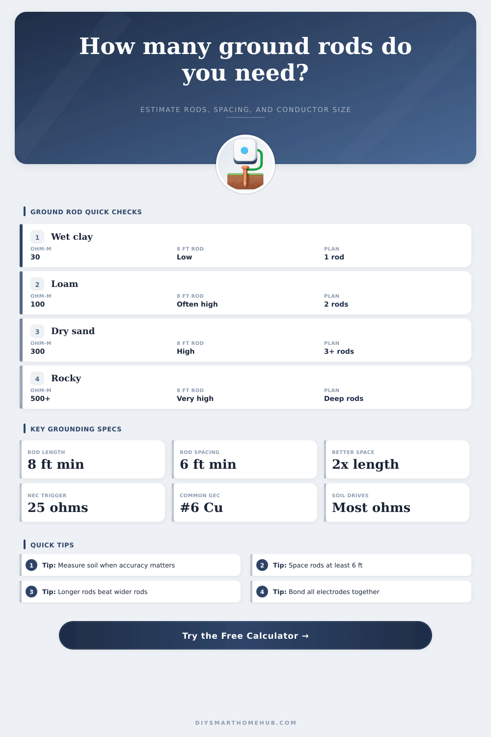
| Rod length in soil | 8 ft minimum contact length | Flags short electrodes | Length has a major effect on calculated resistance |
| Multiple rod spacing | 6 ft minimum | Rates the spacing result card | Close rods overlap electrically and reduce less efficiently |
| Preferred spacing | About 2 times rod length | Improves array efficiency estimate | More separation helps added rods contribute more |
| Single rod trigger | 25 ohms | Sets one-rod or supplemental-rod note | A single rod above this value indicates a supplemental electrode |
| Soil Condition | Typical Resistivity | 8 ft Rod Screen | Planning Response |
|---|---|---|---|
| Wet clay or marshy soil | 20 to 50 ohm-m | Often near target | One rod may screen well, verify by test |
| Moist loam or garden soil | 50 to 150 ohm-m | Often above 25 ohms | Plan a second rod unless measured low |
| Dry sand or gravel | 200 to 500 ohm-m | Usually high | Use wider spacing, longer rods, or other electrodes |
| Rocky or dry fill | 500+ ohm-m | Very high | Resistance targets may need engineered grounding |
| Service Conductor Range | Table Copper GEC | Table Aluminum GEC | Rod-Only Note |
|---|---|---|---|
| Copper 2 AWG or smaller / Aluminum 1/0 or smaller | 8 AWG copper | 6 AWG aluminum | Often upsized to #6 copper for exposure tolerance |
| Copper 1/0 or smaller / Aluminum 2/0 to 3/0 | 6 AWG copper | 4 AWG aluminum | #6 copper is the common rod-only ceiling |
| Copper 2/0 to 3/0 / Aluminum 4/0 to 250 kcmil | 4 AWG copper | 2 AWG aluminum | Rod-only connection is not required larger than #6 copper |
| Copper over 3/0 to 350 kcmil / Aluminum over 250 to 500 | 2 AWG copper | 1/0 AWG aluminum | Other electrodes may require the full table size |
| Rod Type | Typical Diameter | Corrosion Fit | Best Use Screen |
|---|---|---|---|
| Copper-clad steel | 5/8 in or 3/4 in | Good general durability | Common residential service electrode |
| Galvanized steel | 5/8 in or 3/4 in | Moderate corrosion resistance | Dry inland soil where listed for use |
| Stainless steel | 5/8 in or 3/4 in | High corrosion resistance | Coastal or corrosive soil planning |
| Sectional deep rod | 5/8 in or 3/4 in | Depends on material | High-resistivity sites needing extra depth |
| Project Scenario | Typical Soil Input | Likely Primary Result | Secondary Check |
|---|---|---|---|
| Main service in moist clay | 50 ohm-m | Single rod may calculate near 25 ohms | Use local test reading before relying on one rod |
| Smart detached garage | 100 to 150 ohm-m | Two rods commonly screen better | Keep grounding electrode system bonded |
| Outdoor camera or gate pole | 150 to 250 ohm-m | Two or more rods may be estimated | Confirm equipment bonding and surge device requirements |
| Rocky service entrance | 500+ ohm-m | Simple rods may miss low-ohm targets | Consider engineered electrodes and field testing |
To ground a homes or an outbuilding, a grounding rod system is require. The effectiveness of a grounding rod system depend on the soil in which the rods are driven. Soil resistivity are a measurement of how easly electricity move through the soil.
Soil resistivity is the most important variable in a grounding rod system because soil resistivity will determine the resistance of the grounding rod system. Soil resistivity will be low if the soil is damp clay, but soil resistivity will be high if the soil is dry sand. If the soil has a low soil resistivity, the grounding system will work more easy.
Grounding Rods, Soil, and the Calculator
However, if the soil has high soil resistivity, the grounding system will require more rod, more length, or more diameter for the grounding rods to reach the target soil resistivity. Several inputs must be entered into the calculator to determine what the grounding rod system requirements is. You must enter the soil resistivity into the calculator because the soil resistivity will dictate the resistance of the grounding rod system.
The size of the service conductor must be entered into the calculator because the size of the service conductor is based on the largest ungrounded conductor that powers the electrical panel. The electrical code will dictate the size of the service conductor; however, many use a #6 copper conductor for rod-only grounding system. Using a #6 copper conductor for grounding rods is an industry standard because it can survive physical damage and exposure to the element.
Other inputs that will determine what type of grounding rod system will be created are the material and dimensions for the rods. Many use copper clad steel rods for grounding systems for residential projects because they are durable and affordable. For projects in which the soil is likely to be corrosive to steel, you can use stainless steel rods.
However, stainless steel rods are more expensive than copper clad steel rods. The diameter of the rods can be changed in the calculator; however, it will have a small effect on the overall resistance of the grounding rod system. The length of the grounding rods is an important factor in creating an effective grounding system because changing the length of the rods will have a much larger impact on the resistance of the system compared to the diameter of the rods.
Another important input is the spacing between the grounding rods. The electrical code requires that grounding rods be spaced a minimum of six feet apart. However, six feet may not be the best spacing between rods for an effective grounding rod system.
Grounding rods too close together will create overlap in the electrical system that conduct electricity from the grounding rods. Placing grounding rods at a distance equal to the length of the rods will result in a higher resistance of the grounding rod system then if the rods were placed at a distance equal to twice the length of the rods. Therefore, the spacing between grounding rods should be larger than the code requires.
Using the calculator will provide several output regarding the grounding rod system. The number of rods required to reach the target resistance will be one of the output. Another output will let the installer know if the target resistance of the grounding system will be met or missed.
Another important output is the spacing check for the grounding rods. This will indicate whether the rods will follow the electrical code or a better engineering practice. Finally, the calculator will note the grounding conductor and the size of the grounding conductor will be provide.
It should be noted that the calculator will provide helpful number and values regarding the grounding system. However, the calculator will not provide the final test result for the grounding system. The calculator makes the assumption of a uniform soil composition for the grounding system; however, real soil contains layer and moisture at different level.
Because of the way in which soil can change from the specifications provided in the calculator, a grounding system test must be performed in the ground and the authority having jurisdiction must be consulted to ensure compliance with local code. This calculator will remove some of the guesswork in establishing a grounding system; however, it will not replace actual grounding rod system testing in the ground. Some of the mistake that occur in grounding systems include treating the grounding rod system as an afterthought.
For instance, installing an eight-foot grounding rod will produce a resistance that is likely to be higher than twenty-five ohms. Another mistake is to space two grounding rods only six feet apart. If the rods are too close together, they will create overlap in the electrical system.
Using the grounding system calculator will allow an installer to determine these mistake and the effect that they will have on an installation site. The calculator can determine whether the resistance will be ten ohms or twenty-five ohms; both a target for different projects. The reference table included with the calculator can provide additional information for establishing a grounding system.
The tables include information on typical soil resistivity, code minimum length for rods, code minimum spacing between rods, and the size of the grounding conductor. These tables will allow the installer to ensure that using clay soil will require less effort to establish a grounding system than dry sand. The tables will also indicate that rod-only grounding systems will use a #6 copper conductor, regardless of the size of the electrical service.
Another decision that must be made before installing grounding rods is the level of resistance required for the grounding system. Resistance level may differ for various projects. For example, a detached garage may require a higher level of resistance than the main house with sensitive electronics.
Grounding rods may also be required for installing an outdoor camera pole because outdoor camera pole are sensitive to voltage transients. The grounding system calculator will provide the mathematical data that will allow an installer to decide what the final requirements will be for the project. For a grounding system to be successful, the rods, the conductor, and the soil will have to work together to establish the target resistance for the grounding system.