PWM Solar Charge Controller Calculator
Estimate the right PWM controller size from real panel Isc, check whether your module voltage class truly matches the battery bank, and see how much harvest PWM clipping leaves on the table.
📌Preset scenarios
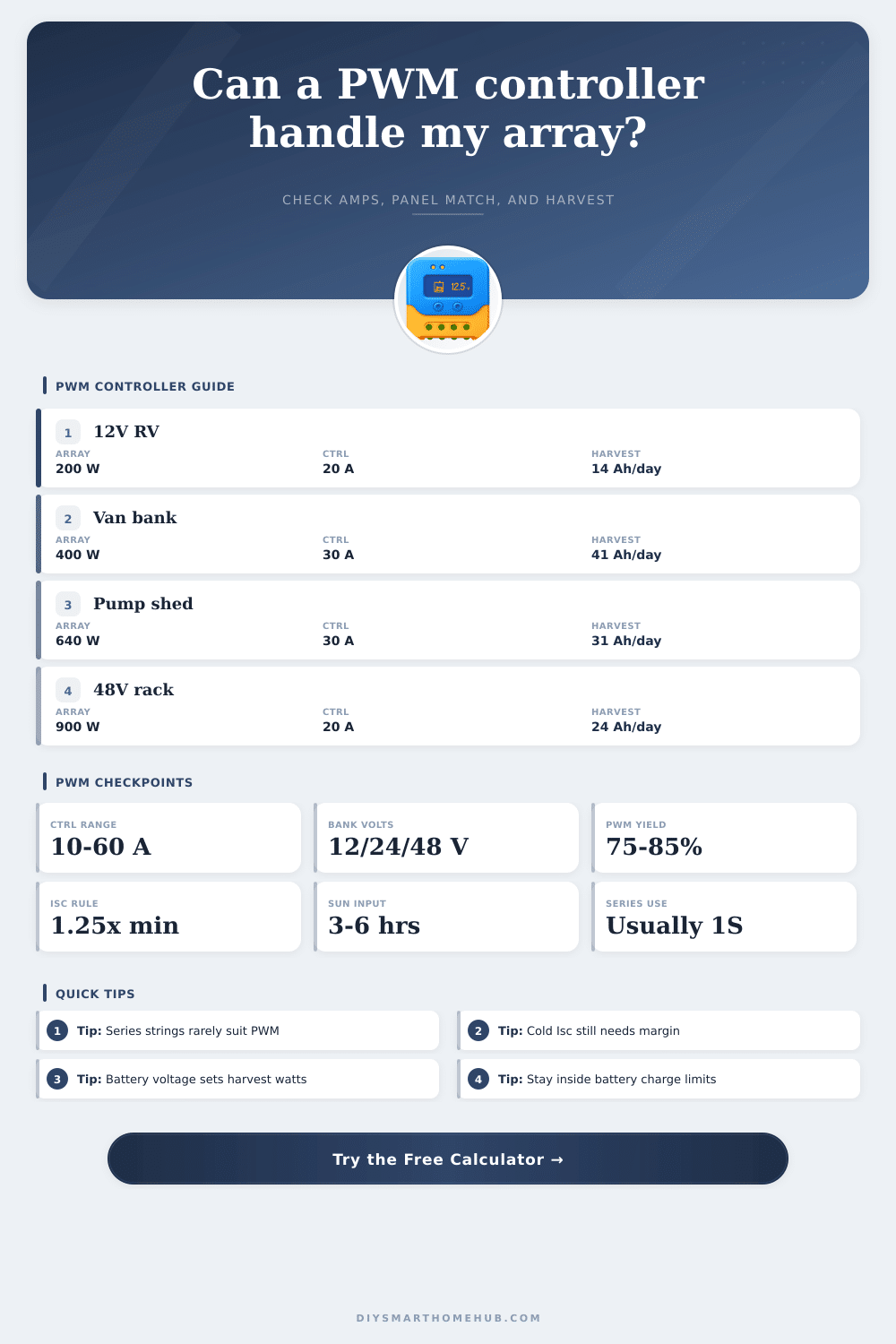
These presets cover maintenance charging, van banks, shed loads, pump systems, and 48 V remote racks. Each preset updates battery size, module class, controller margin, and daily load so you can compare common PWM jobs quickly.
⚡System inputs
PWM controllers care about battery voltage class, total panel current, and the bank's acceptable charge rate. Use the unit toggle to view harvest and storage in amp-hours or watt-hours while the math stays consistent.
📊PWM chemistry quick view
Absorb targets and comfortable charge-rate ranges vary more than many DIY builds assume. These cards give a fast check before you compare panel current to battery bank size.
📑Reference tables
The first table shows panel class fit for PWM use. The second table shows how many common module types usually fit inside common controller ratings when the 125% Isc rule is applied.
| Module | Nominal Bank | Vmp | Isc |
|---|
| Controller | 100 W | 200 W | 320 W |
|---|
📋Preset comparison table
This scenario table summarizes what the included presets roughly ask from a PWM controller before any site-specific wiring losses or seasonal adjustments are added.
| Scenario | Battery Bank | Array | Controller | Daily Harvest |
|---|
🚧PWM planning notes
A 24 V or house-style module can still charge a 12 V bank through PWM, but the controller can only pass current at battery charging voltage, so a large chunk of panel wattage is clipped away.
The same array can be perfect for one bank and underpowered for another. Comparing bulk charge current against the chemistry's healthy C-rate range quickly exposes sluggish or overly aggressive pairings.
A Pulse Width Modulation (PWM) controller are used to control the flow of electricity from the solar panels to the batteries. PWM controllers connects the solar panels to the battery when the voltage from the panels is appropriate to charge the battery. Because a PWM controller essentially works as a switch, it does not monitor the voltage levels from the solar panel array like an MPPT controller.
Thus, if the voltage level from the solar panel are not appropriate to the battery requirements, the PWM controller can result in the battery losing power. Furthermore, if the solar panel has a high voltage but the battery has a low voltage, the PWM controller will reduce the voltage from the panels to that of the battery, which reduce the amount of power generated by the solar panel array. In order to size a PWM controller, use the short circuit current (Isc) of the solar panels as opposed to the peak wattage of the panels.
How to Size and Use a PWM Solar Charge Controller
In order to calculate the total current that the PWM will receive from the solar panel array, multiply the Isc of each individual solar panel by the number of solar panel string that will be connected in parallel to the PWM controller. Additionally, add 25% to that calculation to allow for increased solar panel current with cold weather climates. Add additional margin to the calculated current if the solar panel battery bank will reach elevated temperature or if additional solar panels will be added to the array.
A PWM controller that is sized too small relative to the solar panel array may fail, but a PWM controller that is sized too large will remain idle. The chemistry of the batteries determines the charge rate at which they should be charged, and that charge rate must match the chemistry of the batteries to avoid damaging the batteries. Lead acid batteries should be charged at rates between 5 and 13% of the battery capacity, as charging at incorrect rates will lead to the formation of lead sulfate crystals on the plates of the batteries.
Absorbed Glass Mat (AGM) batteries can handle charge rates of up to 20% of their capacity. Gel batteries require milder charge rates than other battery chemistries, but lithium batteries can handle charge rates of up to 30% of their capacity. Ensure that the charge rate for the batteries is matched to its chemistry; otherwise, the batteries may overheat or undergo sulfation.
The amount of energy that can be harvested by the solar panel array each day is dependent upon the number of peak sun hours in the area, the efficiency of the PWM controller, and the amount of voltage that is lost through the wiring from the solar panel array to the batteries. Energy harvest can be calculated by multiplying the current from the solar panel array by the number of peak sun hours each day. The output of the solar panels will be less than the theoretical amount of energy that can be harvested by the panels; the PWM controller will limit the voltage to that of the battery bank.
Furthermore, additional energy is lost due to the wiring and dirt on the panels; approximately 6% of the energy that can be theoretically harvested by the panels is lost due to these factor. These losses should be calculated to ensure that the solar panels will provide enough energy to power the electrical load of the system each day. Common mistakes that can be made in the installation of a solar panel system that uses PWM controllers includes connecting solar panels that are designed for high voltage to batteries with low voltages.
In these instances, the PWM will clip the voltage of the solar panel array to that of the battery bank, reducing the efficiency of the solar panel system. Additionally, many systems do not account for the 10% increase in short circuit current that occurs in solar panels at cold temperatures. Finally, solar panels are often connected in series with one another with PWM controllers, which increases the voltage of the panel array; high voltages do not work well with PWM controllers.
Instead, solar panels should be connected in series to ensure that the voltage is consistent between the solar panels and the battery bank. In addition to the factors discussed above, there are a few other factors that may affect the performance of the solar panel system. Factors such as shade from trees can reduce the output of the solar array, leading to less electricity produced by the solar panel system.
Additionally, the temperature of the solar panels can affect the amount of energy they output; they may lose approximately 0.4% of their power output for every degree that the temperature of the panels increases above 25 degrees Celsius. Furthermore, in battery banks that contain multiple batteries in parallel, it is necessary to use balanced wiring to ensure that each battery bank receives the same charge as each of the other battery in the bank. Finally, it is necessary to install a fuse close to the PWM controller that is rated to 1.25 times the current that is rated for the PWM controller to protect the system from power surge.