UniFi PoE Budget Calculator
Plan UniFi switch headroom from endpoint power, floor area, cable length, and reserve so you can compare Lite, Standard, and Pro Max switch fits before you buy.
| Endpoint | Max Draw | Min PoE Class | Planning Zone | Best Use |
|---|
| Switch | PoE Ports | PoE Budget | Port Output | Where It Fits |
|---|
| Cable | Resistance | Comfort Run | Drop Bias | Note |
|---|
| Scenario | Endpoint | Switch | Count | Source Need |
|---|
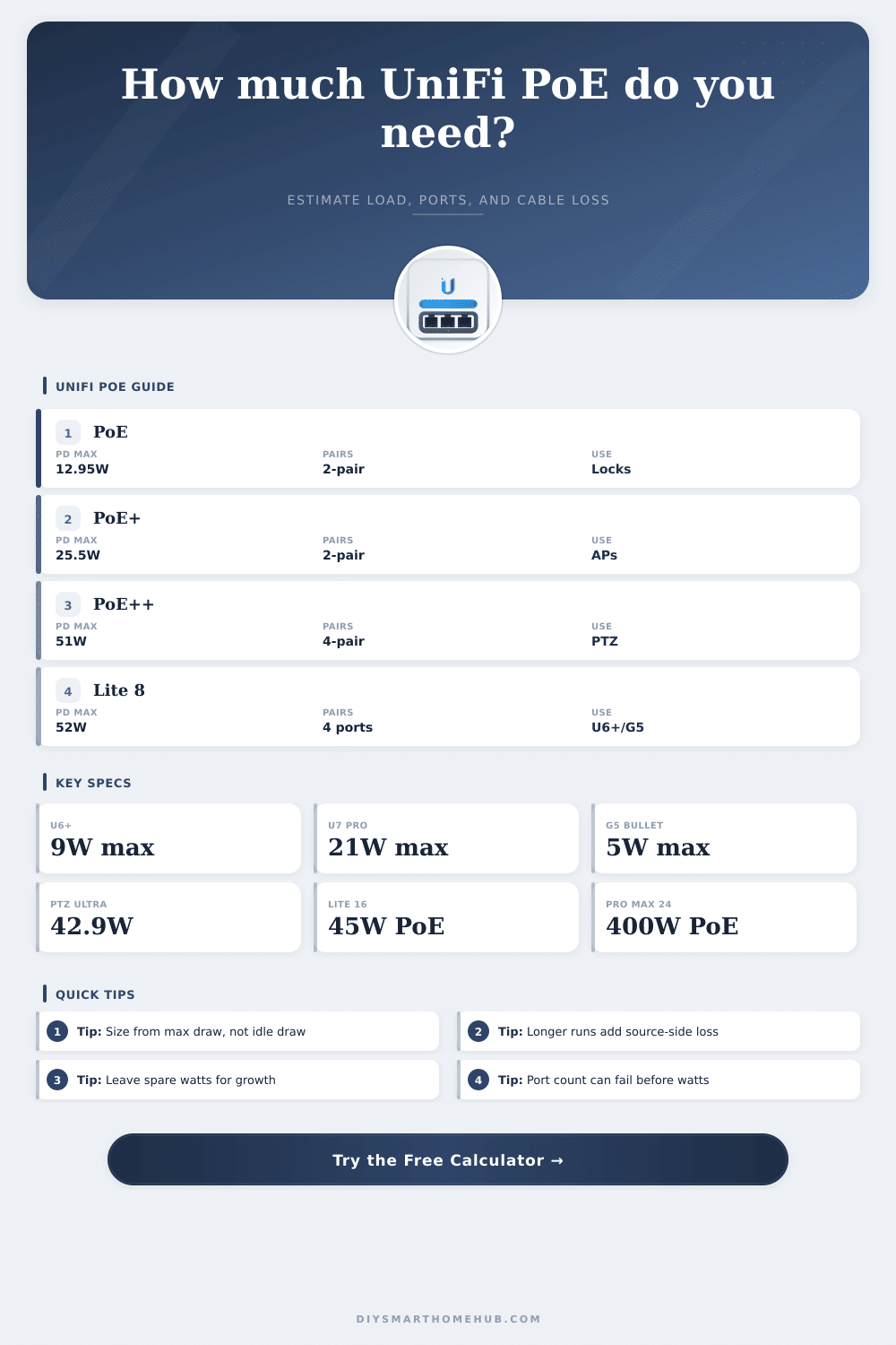
Starting from maximum endpoint draw, then adding cable loss and reserve, keeps the switch plan away from the edge.
A switch can still have spare watts while every powered port is already occupied. This calculator checks both limits together.
Power over Ethernet, or PoE, is a technology that allow data and electrical power to travel along the same Ethernet cable. Power over Ethernet is useful for providing power to devices like wireless access points and security cameras, eliminating the need for electrical outlets near each of these device. Power over Ethernet, however, is limited by mathematics and requires careful planning to ensure that the power switch and the cable can handle the electrical load of the devices.
If you dont plan for the electrical load of the network devices properly, those devices may experience fluctuations in the power that is delivered to them, which may cause them to lose connection from the network. The first step in planning Power over Ethernet is to determine the maximum power draw of each of the devices. Devices like wireless access points draws little power when idle, but may draw significant power when many device are connected to those wireless access points.
How to Plan Power over Ethernet
Similarly, security cameras may draw little power when they are stationary, but draw more power when the cameras are required to move or perform other advanced function. The power draw specifications of each device that Power over Ethernet is to power should use the peak power figure rather than idle power figures. The peak power figures represent the maximum amount of electricity that each device will draw when in use.
The second step in planning Power over Ethernet is to select the cables that will be used in the network. Thinner cables have more higher electrical resistance than thicker cables. High electrical resistance along the cable can lead to a voltage drop along the cable run, which is a reduction in the voltage that reaches the devices along the cable run.
You can use thick cables, or you can reduce the length of the cables to minimize the drop in voltage along the cable. The way that the wire pairs within the cable are used can impact the amount of power that can be delivered to each device. Standards like PoE++ allow for better distribution of power along the wire pair.
Other factors that you should consider in the planning of Power over Ethernet include the density of the devices in the area. In small areas with many device, such as a conference room, the density of devices will be high. High densities of devices require more power from the switch that distribute power to the devices.
In large areas with few device, such as in an open office, the density of devices will be low, but the length of the cables that distribute power to the devices may be longer. Fewer devices in a larger area may mean fewer watts of power are required to power all of the devices in the area, but more power may be required to distribute that power to each device over longer distances. The number of devices can be calculated for each area.
Additionally, the signal from each device will overlap the signal from other devices. Overlap prevents dead spot in the signal, but requires installing more devices to provide such coverage. Thus, more devices require more total power from the Power over Ethernet switch.
The third and final step in planning Power over Ethernet is to select the Power over Ethernet switch. Each switch will have a total wattage that can be distributed to the devices that are connected to the switch, as well as have a certain number of available network port. A switch may have many available network ports, but it might not have enough total wattage to power each device in each port.
Conversely, a switch may have a high total wattage, but it may not have enough available network ports to connect to each of the devices that need to be supplied with power. In either case, a Power over Ethernet switch should of have at least twenty percent of power available as a buffer for any additional devices that may be added to the network. Errors during installation of the Power over Ethernet network can impact the performance of the network.
Bundling of the network cables too tightly may trap heat in the network. Heat increases the resistance of the cables, which can lead to a voltage drop along the cable. Voltage drops along the Power over Ethernet network can reduce the efficiency of the system.
Additionally, more length of cable may be required to install devices in locations where the power supply is already present. An increase in the length of the cable increases the resistance along that cable. Thus, if you plan for the length of the cable, along with the maximum power draw of the devices in the installation, the Power over Ethernet system will remain stable and reliable.