Satellite Dish Focal Point Calculator
Estimate focal length, support arm reach, F/D ratio, rim angle, and approximate dish gain from real reflector dimensions. It works for round, oval, rectangular, and odd custom dishes by converting aperture area into an equivalent circular diameter.
| Surface Type | Base Eff. | RMS Error | Best Fit |
|---|---|---|---|
| Solid Aluminum | 0.66 | 0.35 mm | Ku, X, 5.8 GHz |
| Powder-Coated Steel | 0.63 | 0.45 mm | Ku with good finish |
| Fiberglass Mold | 0.68 | 0.30 mm | Precision home dishes |
| Perforated Steel | 0.60 | 0.55 mm | Outdoor TV reflectors |
| Fine Aluminum Mesh | 0.56 | 1.20 mm | C band and lower |
| Wire Grid | 0.45 | 4.80 mm | Low GHz or UHF work |
| Composite Carbon | 0.72 | 0.20 mm | Tight microwave builds |
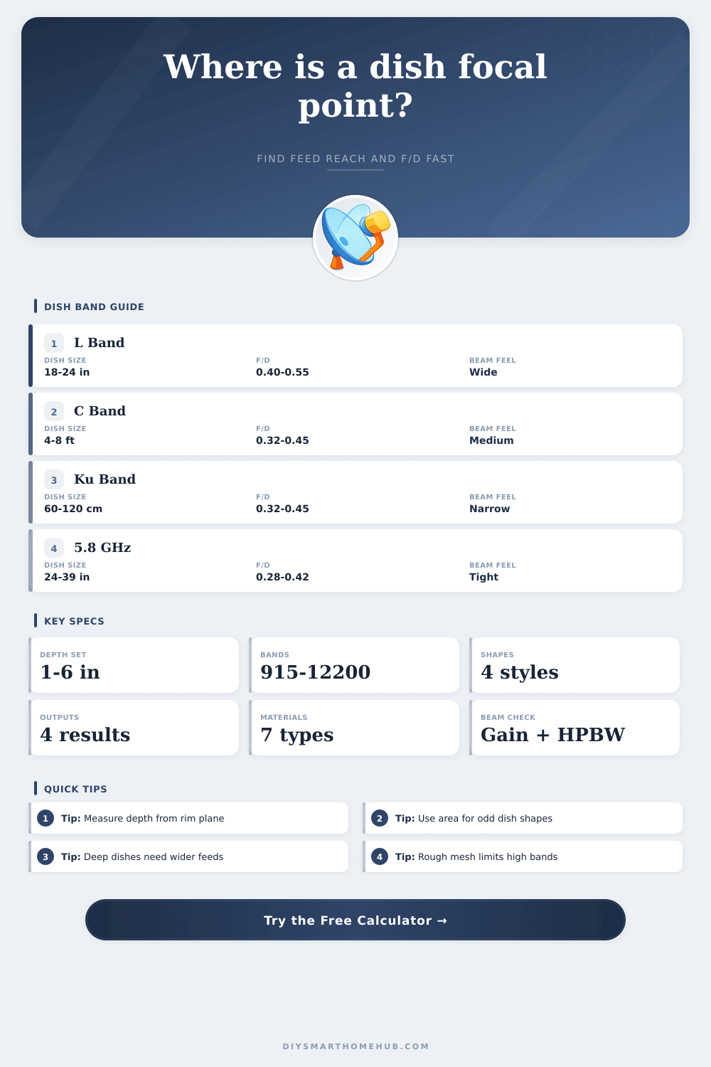
| F/D Range | Dish Feel | Feed Demand | Planning Note |
|---|---|---|---|
| 0.25 to 0.32 | Deep | Wide pattern | Short arm, large rim angle |
| 0.32 to 0.40 | Classic prime | Balanced | Common on round backyard dishes |
| 0.40 to 0.50 | Shallow | Narrower feed | Longer arm and easier feed access |
| 0.50 to 0.60 | Very shallow | Tight pattern | Check edge spill and pointing accuracy |
| Band | Wavelength | Typical Aperture | Beam Feel |
|---|---|---|---|
| 915 MHz | 32.8 cm | 3 to 6 ft | Broad beam |
| 2.4 GHz | 12.5 cm | 18 to 36 in | Moderate aim |
| 5.8 GHz | 5.2 cm | 24 to 39 in | Tight aim |
| 11.7 GHz Ku | 2.6 cm | 60 to 120 cm | Very tight |
| Project | Aperture | Focal Point | Typical Use |
|---|---|---|---|
| 18 in DBS Oval | 18 x 20 in | About 5 in | Compact TV dish |
| 24 in Round Dish | 24 in | About 9 in | FTA Ku setup |
| 26 in Wi-Fi Dish | 26 in | About 10 in | 5.8 GHz backhaul |
| 1.2 m Mesh Dish | 120 cm | About 50 cm | C-band reflector |
A small mistake in the center depth measurement can shift focal length by much more than a small rim error. Stretch a straight edge across the mouth before measuring to the vertex.
A mesh dish that is fine at C band can lose noticeable efficiency at Ku or 5.8 GHz. The calculator uses a Ruze-style surface loss factor to show that tradeoff directly.
A parabolic reflector is a device that reflects signal towards a focal point. The focal point of a parabolic reflector is the point where all of the wave that are reflected from the parabolic reflector will converge. The position of this focal point determine the strength of the signal that is emanate from the parabolic reflector.
If an individual does not position the feed horn of a parabolic reflector at the focal point of the parabolic reflector, then the signal will either be weak or entirely lost. In order to ensure that the signal strength from a parabolic reflector is as strong as possible, it is essential for the individual to have an understanding of the geometry of such a device. The depth of a parabolic reflector is one of the most critical measurements of such a device.
How to Measure and Align a Parabolic Dish
The depth of a parabolic reflector determine its focal length. To obtain the depth of the parabolic reflector, it is essential to take the measurement from the correct plane of the parabolic reflector. To ensure accuracy in measuring the depth, an individual will have to use a straight edge to even out the plane of the dish.
If there is an error in measuring the depth of the parabolic reflector, then the focal length will change. For instance, if there is an error in measuring the depth of a 24-inch parabolic reflector, the feed horn might end up several inch away from the focal point of the parabolic reflector. Furthermore, the depth will determine the F/D ratio of the parabolic reflector.
The F/D ratio will determine the type of feed that are required by the parabolic reflector. The frequency with which the parabolic reflector will be used will have an impact on the way in which the parabolic reflector must be constructed. For instance, if the parabolic reflector will be used to emit high frequency signals, such as Ku-band signals, then the wavelength of the emitted signals will be very short.
Any bump in the surface of the parabolic reflector will reduce the efficiency with which the parabolic reflector can emit the high-frequency signals. While many parabolic reflectors has a mesh structure, the mesh may scatter the high-frequency signals that is emitted by the parabolic reflector due to the size of the holes in the mesh. Aluminum is a better material to construct the mesh than wire mesh.
Additionally, the length of the support arm must be long enough to allow it to clear the curve of the parabolic reflector. Some extra length is required in the support arm to allow for trimming of the support arm to the proper length. For non-circular parabolic reflectors, different calculations must be made to determine the focal length of the device.
However, it is possible to find the equivalent diameter of the non-circular device to calculate its focal length. For instance, an oval shaped parabolic reflector has a specific area that can be converted into an equivalent diameter that can be used in calculating the strength of the signal that is emanated from that non-circular parabolic reflector. Another important factor relating to the performance of a parabolic reflector is it’s rim angle.
Deep parabolic dish have wide rim angles, meaning the feed horn has to illuminate the edges of the dish. Shallow parabolic reflectors have narrow rim angles, which means the shallow dishes has to be more precisely pointed to aim the signal correctly. The physical factor that relate to the performance of a parabolic reflector include the surface of the dish.
Parabolic dishes with a rough surface will lead to surface loss in the dish, which will lead to an increase in the beamwidth of the signal. The physical factor of mesh is also often present in parabolic dishes. The mesh may allow the signal to pass through at C-band frequencies, but it may not allow the signal to pass at higher frequency.
Another physical factor is the effect of wind on large parabolic reflectors. The physical effect of wind causing the dish to wobble can create disruption in the signal. Deep parabolic reflectors allow for shorter support arm for the dish.
However, the feeds have to have a broad illumination pattern to reach the edges of the deep parabola. Shallow parabolic reflectors require longer support arms, which may sag if not provided with extra support to maintain the necessary alignment. To avoid these common mistake in the installation of a parabolic dish antenna, follow these specific measurement rules.
Do not measure the diameter of the flange of the dish; this will result in an incorrect calculation of the area of the dish and its focal length. Avoid cutting the support arms to an exact length; the feed horn should not come short of the phase center of the antenna element. Consider the illumination taper of the feed horn; if the illumination taper of the feed horn does not match the physical parameter of the parabolic dish, the antenna system will lose gain.
To ensure that a parabolic reflector functions as it should, use a tool to calculate the focal length, the arm reach of the support stand for the feed horn, and the equivalent area of the dish. Calculate the focal length from the bottom of the parabolic dish, and include a buffer in your calculation of the arm reach for the support stand. These calculations will allow you to calculate the gain of the antenna and its beamwidth.
The beamwidth will allow you to calculate the amount of error that is allowed in aiming the dish. Finally, to fully test the installation of the parabolic antenna, use a signal meter to test the alignment of the antenna’s reflector and the feed horn’s horn should be aligned to the correct focal point of the parabolic reflector.