Cable Tray Offset Calculator
Plan simple offsets, rolling offsets, and four-bend saddles around ductwork, beams, and piping so you can estimate bend travel, straight runback, and developed tray length before ordering fittings.
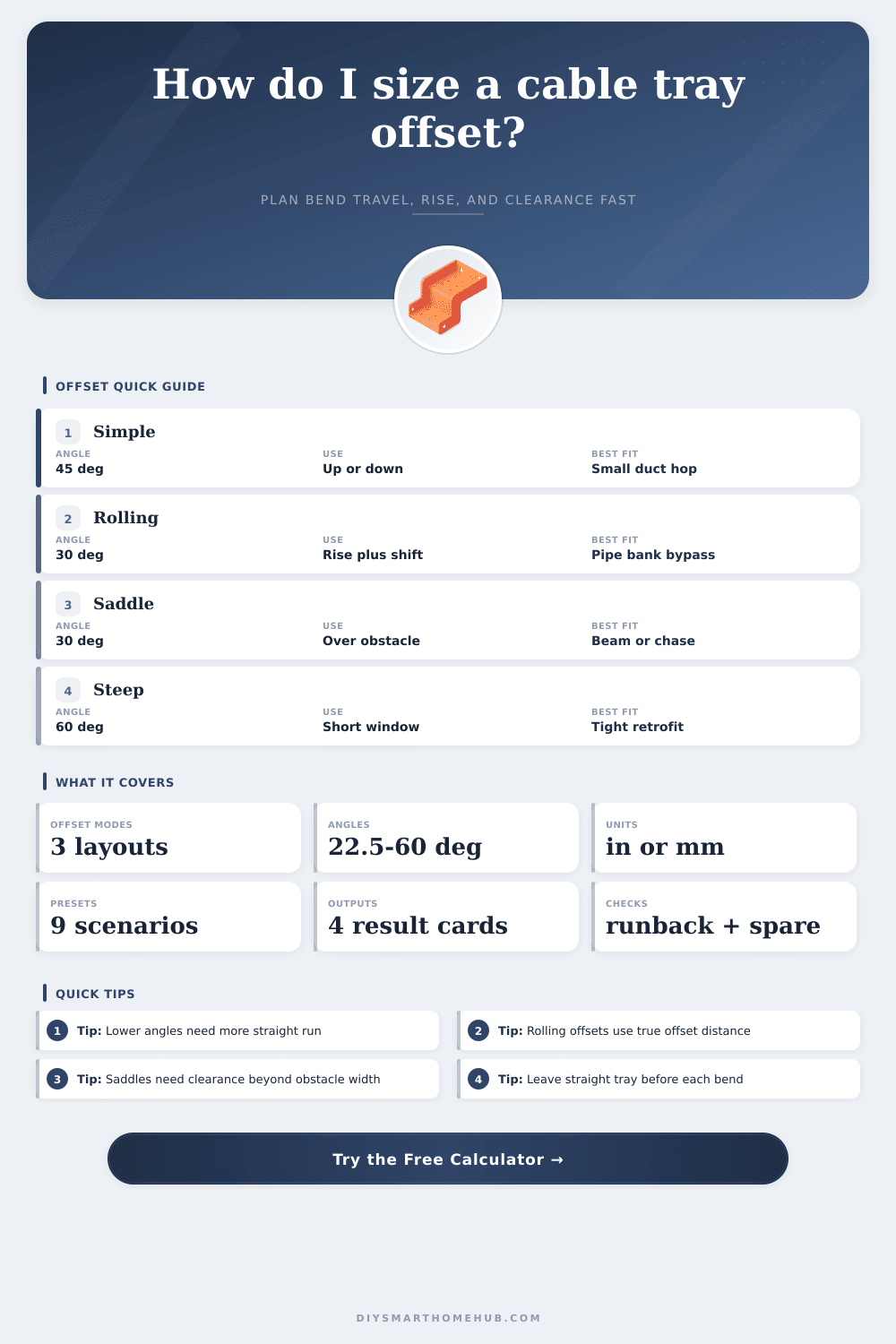
Simple offsets use a single rise or drop with two equal bends. Rolling offsets combine rise and side shift into one true offset distance. Four-bend saddles add a crossing section over the obstruction plus two matching offsets.
Offset Breakdown
| Angle | Travel Multiplier | Runback Multiplier | Best Use |
|---|---|---|---|
| 22.5 deg | 2.613 x true offset | 2.414 x true offset | Gentle large-tray offsets with lots of run length |
| 30 deg | 2.000 x true offset | 1.732 x true offset | Balanced field-fit angle for most tray work |
| 45 deg | 1.414 x true offset | 1.000 x true offset | Compact offsets where pull path is still acceptable |
| 60 deg | 1.155 x true offset | 0.577 x true offset | Tight retrofit work where run window is limited |
| Tray Style | Preferred Angle | Suggested Straight Stub | Typical Offset Use |
|---|---|---|---|
| Ladder tray | 30-45 deg | 1.5 x tray width | Main low-voltage trunk and feeder transitions |
| Wire basket tray | 45 deg | 1.25 x tray width | Retrofit side shifts around ducts and framing |
| Ventilated trough | 30 deg | 1.75 x tray width | Mixed cable saddles with cleaner support under the crossing |
| Solid-bottom tray | 22.5-30 deg | 2.0 x tray width | Shielded or finished-space crossings with lower bend stress |
| Channel tray | 45-60 deg | 1.0 x tray width | Single branch bypasses and short device drops |
| Center-spine tray | 30 deg | 1.75 x tray width | Single-row overhead pathways with careful fitting spacing |
A rolling offset is not just the rise plus the side shift. Use the diagonal true offset first, then apply the angle multiplier so the leg length is not undersized.
22.5 degree and 30 degree fittings are easier on cable pulls, but they consume much more runback than a 45 degree or 60 degree offset.
The suggested straight stub is based on tray width and style so there is still room to place splice hardware without crowding the tangent points.
Beam and chase crossings work better when the top crossing clears both sides of the obstruction instead of dropping directly onto the edge of the steel or duct wrap.
When you installs a cable tray in a mechanical room, you might encounter an obstacle in the form of an HVAC duct that prevents the tray from continuing forward along its path. When a cable tray encounter an obstacle, an offset must be used to allow the tray to rise over the obstacle or shift to the side of the obstacle in a way that allows the tray to return to its original plane. The math that is performed to calculate the offset that the tray should make is crucial to the installation of the tray; if the offset is calculate incorrectly, the cables may become bound within the tray, or the tray supports may clash with the couplers that joins the different sections of tray.
The true offset distance is the distance from the starting point of the offset to the finishing point of the offset. If the tray make two bend to go over an obstacle, the true offset distance is the vertical rise of the tray over the obstacle and the drop from the obstacle to the rack. If the offset also incorporates a lateral shift, the true offset distance is the hypotenuse of the rise of the offset squared plus the shift of the offset squared.
How to Measure and Install Cable Tray Offsets
The true offset distance must be calculated accurate; if the true offset distance is undersized, the tray will be too short to clear the obstacle. If the true offset distance is oversized, the tray will contain waste in the material for the tray. Another factor in determining the offset of the tray is the bend angle of the offset.
If 30 degree bend are used, the cables will have a smoother path through the tray; 30 degree bends are also beneficial for fiber optic bundle, as fiber optics has low bend radius specifications. However, the required length of tray for 30 degree bends is twice the length of the same offset with 45 degree bends. If 60 degree bends are used, the tray will have a smaller footprint; this is beneficial for retrofit project.
However, the tray has to be installed with precise tangent points; otherwise, the tray hardware will become crowded. The style of the tray may also impact the choice of angle for the bends. For example, ladder trays work best with 30 to 45 degree angle; the tangents of the tray are long enough for splice plates.
Wire basket trays and channel trays can have steeper bends because the wire mesh or rail can take the specified radius. When installing trays over the flange of a beam, the clearance has to be calculated. The clearance must account for the depth of the tray; otherwise, the tray will be too close to the obstacle.
The developed length of the offset should account for four travel legs of the tray and the section of the tray that cross the obstacle. The developed length of the offset must be pre-calculated; otherwise, the installer will not know whether the run of the tray will be smaller than the support rules. Many installers makes mistakes with the calculation of the offset of the tray.
One of the most common mistake is measuring the rise of the obstacle only to the edge of the obstacle; they do not account for the depth of the tray. Another common mistake is treating each shift of the tray that is rolled around an obstacle as separate offset; they should be treated as if they form one diagonal plane of the tray. Another mistake is using low angles for the bends; they will require a longer runback for the tray to return to its original plane; this could prevent the tray from being installed through a narrow corridor.
Using steep angles for the bends will create high tension on the cables; this can be harmful to pre-terminated fiber. Additionally, 3 to 8 percent must be allowed for the splices; this allowance will account for any trim to the lengths of the cables. The width of the tray will impact the lengths of the tray that are required to be installed in a straight line.
If the tray is wider, the length required for the tray to make a turn. The wider the channel tray, the more length for the tray to incorporate any tray dividers. The narrower the channel tray, the less length are required for the tray to remain installed in a straight position.
The bends in the tray should also be monitored; if the tray makes a bend that has too many splice in it, the tray will have weakened pull characteristics and may violate the rules for the amount of fill that the tray cavity allow. The angles for the offset should be chosen according to the specifications of the tray that will be used and the specifications of the cables. For example, ladder trays may be used with medium angles for feeder trunks.
However, solid-bottom trays will have shallow bends to protect the shielded cable run from stress created by the cover. If a saddle tray is used over a wide beam, the clearance must be sufficient for the bulky bundles of cable. Finally, the direction in which the cables are to be pull should be planned.
Cable trays with offsets will have high points for the cable; the pulls should be planned to go downhill in the direction of the highest point, or rollers should be installed at those high points for the cables to travel along.