Cable Tray Ampacity Calculator
Estimate corrected conductor ampacity for tray runs by combining NEC-style base ampacity data with insulation temperature rating, ambient correction, current-carrying conductor count, tray airflow, and cable arrangement.
Load a common smart home or residential power scenario, then fine-tune tray size, conductor count, and ambient temperature.
Results appear here after calculation.
These reference values keep the planner anchored to familiar conductor sizes and tray airflow patterns. Final equipment terminals and local code rules can still govern the allowable ampacity.
| Size | Cu 90C Base | Al 90C Base | OD | Typical Tray Duty |
|---|---|---|---|---|
| 12 AWG | 30 A | 25 A | 0.13 in | 20 A branch circuits |
| 8 AWG | 55 A | 45 A | 0.22 in | Heat pump and EV branches |
| 4 AWG | 95 A | 75 A | 0.32 in | Workshop and subfeed runs |
| 1/0 AWG | 170 A | 135 A | 0.46 in | Detached office feeders |
| 4/0 AWG | 260 A | 205 A | 0.63 in | Battery and service links |
| 500 kcmil | 430 A | 350 A | 0.95 in | Large parallel feeder banks |
| Tray style | Factor | Airflow | Planning note |
|---|---|---|---|
| Ladder tray | 1.00 | Highest | Baseline open tray condition for the planner. |
| Wire mesh basket | 0.98 | High | Open sides cool well but tighter wire geometry trims a little margin. |
| Ventilated trough | 0.95 | Medium | Perforated bottoms still hold more heat than ladder rungs. |
| Solid bottom tray | 0.90 | Lower | Use extra caution when ambient temperature is already elevated. |
| Project | Tray | Conductor set | Design load | Why it matters |
|---|---|---|---|---|
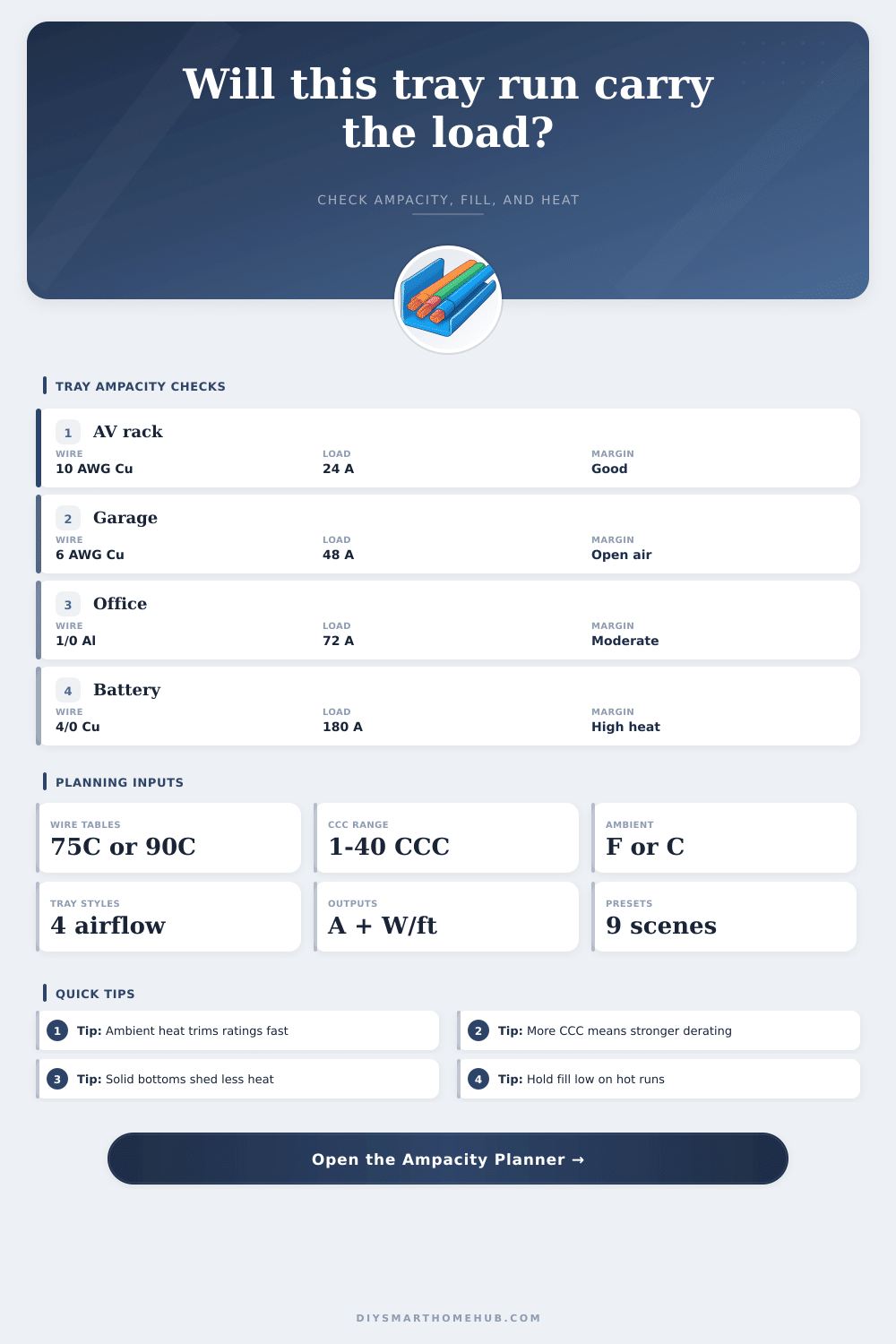
| Rack branch | 6 in ladder | 3 x 10 AWG Cu | 24 A | UPS and amp racks run warm for long hours. |
| Garage subpanel | 8 in ladder | 3 x 6 AWG Cu | 48 A | Power tools add intermittent peaks and dust heat. |
| Solar AC feeder | 10 in trough | 3 x 2 AWG Al | 72 A | Outdoor enclosures often raise conductor temperature. |
| Battery inverter | 12 in ladder | 4 x 4/0 Cu | 180 A | High DC current multiplies heat per foot quickly. |
| Detached office | 300 mm basket | 3 x 1/0 Al | 72 A | Long runs benefit from both ampacity and loss checks. |
Tray runs above attics, in garages, or beside inverter gear often operate hotter than the room around them. Using a hotter planning ambient keeps the correction factor honest.
A run can pass the current check and still crowd the tray. Low fill leaves more air around insulated conductors and usually preserves future expansion room.
Ampacity of a cable tray are the measurement of how much electrical current the cable tray can carry without the cables overheating. To determine the ampacity of the cables inside a cable tray, you must understanding how much heat builds up in the tray and how much heat escape from the tray. Heat is generated as a result of an electrical current that pass through the conductors.
If the current dont manage the heat generated correctly, the insulation on the conductors will fail. Another factor to consider that can impact the heat that escapes from the conductors is the physical design of the cable tray. For example, ladder cable trays allow for air to circulate around the conductors, and the rungs of the ladder tray do not obstruct the movement of air.
What affects cable tray ampacity
Solid bottom cable trays, on the other hand, will trap the heat near the conductors and increase the temperature of the electrical current in the conductors. If you use a solid-bottom cable tray, the electrical current will reach a more higher temperature then if you used a ladder cable tray. The number of conductor within the cable tray will also have an impact upon the ampacity of that tray.
If there are a great number of conductor within a tray, the conductors will trap the heat produced by the electrical current that pass through them. As a result, you will have to derate the ampacity of the conductors to accommodate for the increased heat. If there are few conductors within the tray, the heat will be able to escape the conductors easy.
However, if there are many conductors within a tray, the heat will build up quick. For example, twenty conductors will have a lower ampacity than three conductor within the same cable tray. Ambient temperature will also have an impact upon the ampacity of the conductors within a cable tray.
The ambient temperature is the temperature of the air surrounding the cables within the cable tray. If the ambient temperature of the area around the tray is higher than 30C, the air will not be able to effectivly carry away the heat produced by the current within the conductors. In this case, you will have to decrease the ampacity of the conductors.
For example, if the cables are install in a particularly hot environment, such as within an attic, the temperature of the conductors will be higher than if they were install in a cooler location. The insulation rating of the conductors will also have an impact upon ampacity. Some conductor have a 90C insulation rating, meaning they can tolerate high temperatures.
Other conductors have a 75C insulation rating; their insulation is less able to tolerate heat. You will have to derate these conductors to accommodate for the higher temperatures. Another factor to consider is the way in which you arrange the conductors within the cable tray.
If you place the conductors within a single layer, there will be more even shedding of heat from the conductors. If you place conductors in two layers, the bottom layer will reach higher temperatures then the top layer. Additionally, if you lace your conductors or form trefoil group, less air will be able to move around the conductors.
This will lead to a reduction in the ampacity of the conductors within the cable tray. Fill capacity is one of the most important measurement for a cable tray. Fill capacity is the measurement of how much of the internal space of the cable tray is taken up by the conductors.
If there is too much fill capacity within a tray, the conductors will be too crowded for adequate movement of air around them. To ensure that conductors do not become too hot, the conductors should occupy under 40 percent of the total area of the cable tray. Lastly, you must consider whether or not the load for the conductors is a continuous load.
Continuous loads are electrical loads that operate for three hour or more, such as electric vehicle charger. If the load for the conductors is a continuous load, you will only be able to use 80 percent of the rated ampacity of the conductors. This is to prevent the conductors from overheating and damage the insulation on the conductors.
Finally, ensure that there is a reserve of between 10 and 20 percent of the calculated load to provide for potential change to the cable tray and to account for potential measurement error.