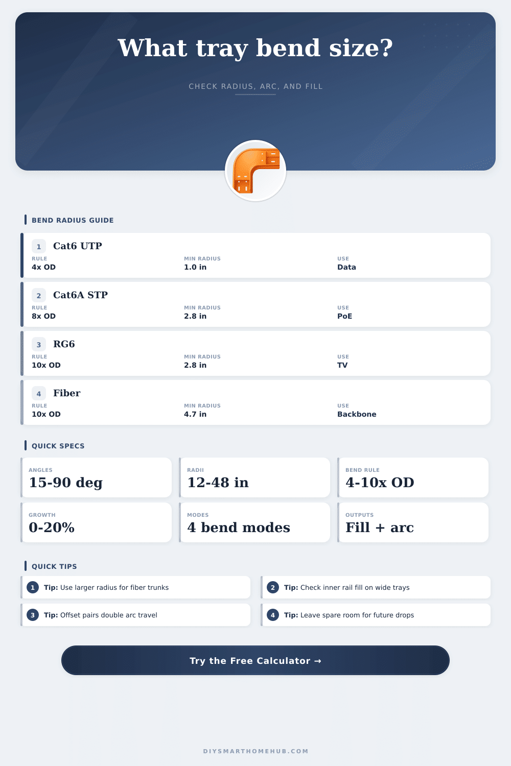
Cable Tray Bend Calculator
Estimate elbow arc length, setback, inner-rail crowding, and cable bend-radius compliance before you route low-voltage tray turns through racks, soffits, risers, and whole-home backbones.
The calculator uses tray width, centerline radius, bend family, cable outside diameter, and growth-adjusted fill to show how much tighter the inner rail becomes than a straight run.
Calculation Breakdown
| Cable Type | Typical OD | Installed Min Radius | Typical Smart Home Use |
|---|---|---|---|
| Cat6 UTP | 0.24 in / 6.1 mm | 4 x OD = 0.96 in | Rooms, TVs, access points |
| Cat6A shielded | 0.35 in / 8.9 mm | 8 x OD = 2.80 in | High PoE cameras and uplinks |
| RG6 coax | 0.275 in / 7.0 mm | 10 x OD = 2.75 in | TV feeds and cable modems |
| 16/4 speaker | 0.30 in / 7.6 mm | 8 x OD = 2.40 in | Distributed audio and keypads |
| 22/4 security | 0.18 in / 4.6 mm | 6 x OD = 1.08 in | Sensors, contacts, and readers |
| Indoor fiber trunk | 0.47 in / 11.9 mm | 10 x OD = 4.70 in | Backbone and inter-rack links |
| Angle | Center Arc at 12 in Radius | Setback | Best Use |
|---|---|---|---|
| 15 deg | 3.14 in / 80 mm | 1.58 in | Small alignment correction |
| 30 deg | 6.28 in / 160 mm | 3.22 in | Wall bypass and branch turn |
| 45 deg | 9.42 in / 239 mm | 4.97 in | Rack and ceiling transitions |
| 60 deg | 12.57 in / 319 mm | 6.93 in | Sharper utility room sweep |
| 90 deg | 18.85 in / 479 mm | 12.00 in | Full corner elbow |
| Tray Style | Effective Fill Factor | Typical Bend Radius Floor | When It Fits Best |
|---|---|---|---|
| Ladder tray | 1.00 | 18 in and up | Main backbone with frequent access |
| Ventilated trough | 0.96 | 12 in and up | Mixed copper and fiber bundles |
| Wire mesh basket | 0.92 | 8 in and up | Fast ceiling routing around framing |
| Solid bottom tray | 0.88 | 12 in and up | Finished spaces needing cleaner containment |
| Channel tray | 0.80 | 6 in and up | Short security or device branches |
| Project Scenario | Tray | Radius | Why It Is Common |
|---|---|---|---|
| Rack 45 sweep | 6 in basket | 12 in | Short top-of-rack path into a ladder trunk |
| Media room elbow | 12 in trough | 18 in | Bundles AV, data, and coax before drywall |
| Fiber riser bend | 6 in solid | 24 in | Keeps optical trunks gentle in a vertical turn |
| Whole-home core | 18 in ladder | 36 in | Handles dense low-voltage backbones cleanly |
A wide tray with a small centerline radius can still pinch the inner rail badly. The wider the tray gets, the more the shortest cable path crowds on the inside of the elbow.
Two smaller bends can clear framing cleanly, but the total arc doubles and the fill penalty stacks. That matters when a tray already carries spare camera, WiFi, or fiber capacity.
When installing cable tray for low-voltage cabling, the geometry of the bend in the trays must be considered. While cable tray is used to support the cables, the bend in the tray will affect how many cables can be included within the tray. Due to the fact that the cables that are located on an inside of the bend have to travel a shorter distance than the cables on the outside of the bend, the cables will tend to crowding together on the inside rail of the tray.
Should this happen, the cables could reach a fill capacity that exceeds that of the tray. Therefore, it is important to calculate the fill capacity of the tray according to the inside radius of the bend rather than the centerline radius of the tray bend. The type of cable trays that you decide to use will also play a role in the behavior of the cables within those trays.
Cable Tray Bends and How Many Cables Fit
For example, installers often use ladder tray for backbone cabling due to the ability to access the rungs of the tray. Additionally, ventilated trough trays are often used for data, coax and fiber optic cables, though the slats within the trough trays will reduce the amount of space for the cables. Wire mesh basket is often used for ceiling systems due to the ease of installation, but due to the nature of the mesh, there is less fill capacity for the tray.
Channel trays are generally used for security systems and smaller cables, but they can become restrictive if too many bundle of cables are placed within a channel tray. Each of the tray types have a minimum bend radius at which they must be installed. The type of cable that you choose to install within the tray will determine the minimum radius at which that cable can bend.
For example, Cat6 UTP cables can bend to a radius that is four times the outer diameter of the cable. Shielded Cat6A cables have to bend to a radius that is eight times the outer diameter of that cable. Coax cables must bend to a radius that is ten times the outer diameter of the coax cable; bending that cable too tight will crush the dielectric within the coax cable.
Fiber optic cables also have to bend to a large radius to avoid signal loss. When installing many types of cables within one tray, the fill radius must meet the requirements of the largest diameter of cable. Finally, it is also important to provide for the future growth of that network.
It is a common practice to provide a growth buffer of 10 to 20 percent for the number of cables that will be installed within the tray. For instance, if the tray is filled to 40 percent of its capacity in a straight section, that percentage will increase when the cables reach the bend within the tray. Therefore, to account for this increase in fill percentage at the bend, it is better to provide a lower percentage of fill within the straight section.
Should you leave 15 percent of the tray empty for potential growth in the number of cables needed by the network, youll have an easier time using the tray for adding more cables to the system. However, there are some mistakes that should be avoided during the installation of the tray. For instance, using a tight radius for the bends in the tray will cause the cables to crowd together on the inside of those turn.
Additionally, installing vertical drop in the trays without installing dividers will allow the cables within those vertical sections to sag toward the inside of the drop. Furthermore, using offsets in the tray to go around beams in the ceiling will double the length of that bend; the longer the radius of the bend in the tray, the more difficult that it will be to service those cables in the future. Thus, it is important to ensure that the inside path radius of each of the bends within the tray is equal to the diameter of the largest cable that will be installed in that system.