⚡ Impedance Transformer Calculator
Calculate turns ratio, winding impedance, reflected impedance & matching networks for RF and audio transformers
| Impedance Ratio (Z₁:Z₂) | Turns Ratio (N₁:N₂) | Voltage Ratio | Typical Application |
|---|---|---|---|
| 1:1 | 1:1 | 1:1 | Isolation / Balun |
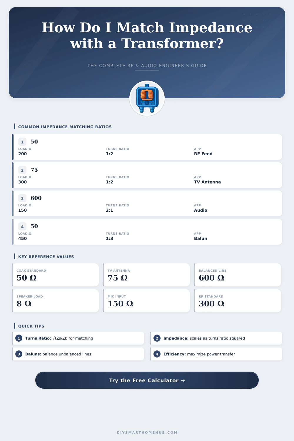
| 1:4 | 1:2 | 1:2 | 50Ω to 200Ω Balun |
| 1:9 | 1:3 | 1:3 | 50Ω to 450Ω Unun |
| 1:16 | 1:4 | 1:4 | 50Ω to 800Ω |
| 4:1 | 2:1 | 2:1 | 600Ω to 150Ω Audio |
| 9:1 | 3:1 | 3:1 | 450Ω to 50Ω Unun |
| 75:1 | 8.66:1 | 8.66:1 | 600Ω to 8Ω Speaker |
| 1:6 | 1:2.45 | 1:2.45 | 75Ω to 450Ω |
| Core Material | Freq Range | Permeability (μr) | Best For |
|---|---|---|---|
| Ferrite Mix 43 | 1–300 MHz | 850 | HF Baluns / EMI |
| Ferrite Mix 61 | 10–200 MHz | 125 | VHF RF Transformers |
| Ferrite Mix 31 | 1–100 MHz | 1500 | Broadband HF Baluns |
| Iron Powder #2 | 1–30 MHz | 10 | HF Inductors / Filters |
| Iron Powder #6 | 10–40 MHz | 8 | VHF Low-Loss |
| Laminated Si-Steel | DC–1 kHz | 5000 | Power / Audio |
| Amorphous Metal | 1 kHz–1 MHz | 10000+ | Precision Audio / SMPS |
| Air Core | Broadband | 1 | RF Broadband |
| SWR | Reflection Coeff (Γ) | Return Loss (dB) | Mismatch Loss (dB) |
|---|---|---|---|
| 1.0:1 | 0.000 | ∞ | 0.000 |
| 1.1:1 | 0.048 | 26.4 | 0.010 |
| 1.5:1 | 0.200 | 14.0 | 0.177 |
| 2.0:1 | 0.333 | 9.5 | 0.512 |
| 3.0:1 | 0.500 | 6.0 | 1.249 |
| 5.0:1 | 0.667 | 3.5 | 2.553 |
| 10.0:1 | 0.818 | 1.7 | 5.441 |
The impedance of a Transformer is one of those topics that is often mentioned but always poorly understood. It does not limit to simple info on the nameplate. Basically the impedance resists the electricity when the Transformer is connected to an AC power source, which causes voltage drop through the coils.
How does one measure it properly? One short-circuits the secondary terminals, then slowly raises the voltage on the primary side, until one reaches the rated electricity of the Transformer. That test voltage divided by the rated voltage gives the percentage of impedance.
What Is Transformer Impedance and How to Measure It
At distribution Transformers, that percentage usually falls between four and six percent. At power Transformers, it normally reaches from six to eight percent.
Here is a quick example. Assume that a Transformer is rated at 20 kVA with 4800 volts on the primary and 240 volts on the secondary. When the secondary is short-circuited, it requires 96 volts to reach the rated primary electricity of 4.2 amps.
From that one can calculate the percetnage of impedance and the available fault electricity. Another example: if a Transformer has a series impedance of eight percent marked on the nameplate, that means that eight percent of the rated coil voltage is needed to produce the rated electricity of the Transformer.
This is very important for safety. The impedance affects the biggest electricity during short circuit that a Transformer can give. The bigger the impedance, the less big that maximum short-circuit electricity.
Protective systems in networks are designed according too fault electricity, that depends on values of impedance. So, knowing the impedance helps to estimate the right fault electricity at short circuit.
Now, some folks think that Transformers do not truly own impedance. They have only a turns ratio instead. A Transformer labeled as 4400 ohms to 8 ohms does not mean that those impedances truly exist.
It simply shows that if one puts 8 ohms on the secondary, the apparent load on the primary will seem like 4400 ohms to the driving source. The voltage source on the primary side sees impedance equal to the actual impedance of the load divided by the square of the turns ratio.
The type of insulation, whether oil or dry, does not have relation with the value of percent impedance. That value deals with impedance through the whole coil, so the coil does not care whether it sits in oil or air. Interestingly, a Transformer can match low or high impedance of microphones to high or low impedance of input points.
Matched impedance gives more sound in audio setups. There are also only two ways to change what a Transformer reflects: change the turns ratio by rewinding or change the impedance on the primary side, so thatthe reflected impedance becomes the wanted value.