⚡ Transformer Inrush Current Calculator
Estimate startup surge current, full-load amps, and protection device sizing for single-phase & three-phase transformers
| kVA Rating | FLA @ 208V | FLA @ 480V | FLA @ 4160V | Typical %Z | Inrush @ 10x (480V) |
|---|---|---|---|---|---|
| 15 kVA | 41.6 A | 18.0 A | 2.1 A | 2–3% | 180 A |
| 30 kVA | 83.3 A | 36.1 A | 4.2 A | 2–3% | 361 A |
| 45 kVA | 124.9 A | 54.1 A | 6.2 A | 2–3% | 541 A |
| 75 kVA | 208.2 A | 90.2 A | 10.4 A | 3–5% | 902 A |
| 112.5 kVA | 312.3 A | 135.3 A | 15.6 A | 3–5% | 1353 A |
| 150 kVA | 416.4 A | 180.4 A | 20.8 A | 3–5% | 1804 A |
| 225 kVA | 624.6 A | 270.6 A | 31.2 A | 4–6% | 2706 A |
| 300 kVA | 832.8 A | 360.8 A | 41.6 A | 4–6% | 3608 A |
| 500 kVA | 1387.9 A | 601.4 A | 69.4 A | 4–6% | 6014 A |
| 750 kVA | 2081.9 A | 902.1 A | 104.1 A | 5–6% | 9021 A |
| 1000 kVA | 2775.8 A | 1202.8 A | 138.8 A | 5–7% | 12028 A |
| kVA (3+ Phase) | FLA @ 480V | 125% FLA (NEC) | Recommended CB | Time-Delay Fuse |
|---|---|---|---|---|
| 15 kVA | 18.0 A | 22.5 A | 25 A | 25 A TD |
| 30 kVA | 36.1 A | 45.1 A | 50 A | 45 A TD |
| 45 kVA | 54.1 A | 67.6 A | 70 A | 70 A TD |
| 75 kVA | 90.2 A | 112.8 A | 125 A | 110 A TD |
| 112.5 kVA | 135.3 A | 169.1 A | 175 A | 175 A TD |
| 150 kVA | 180.4 A | 225.5 A | 225 A | 225 A TD |
| 225 kVA | 270.6 A | 338.3 A | 350 A | 350 A TD |
| 500 kVA | 601.4 A | 751.8 A | 800 A | 800 A TD |
| Duration (Cycles) | Time @ 60 Hz | Time @ 50 Hz | Typical Inrush % | Protective Device Impact |
|---|---|---|---|---|
| 1 cycle | 16.7 ms | 20.0 ms | 100% peak | Instantaneous trips possible |
| 3 cycles | 50 ms | 60 ms | 70–80% | Fast MCCBs may trip |
| 6 cycles | 100 ms | 120 ms | 40–60% | Standard time-delay safe |
| 12 cycles | 200 ms | 240 ms | 20–40% | Normal operation range |
| 18 cycles | 300 ms | 360 ms | 10–20% | Near normal operation |
| 30 cycles | 500 ms | 600 ms | 5–10% | Essentially normal load |
Turn the switch of the Transformer for the first time, and something truly wild happens. A massive increase of current floods in it, that is the term for Inrush Current. It is made up of an initial burst of energy that rushes through the device when you turn on the Transformer or when the energy restarts after a pause.
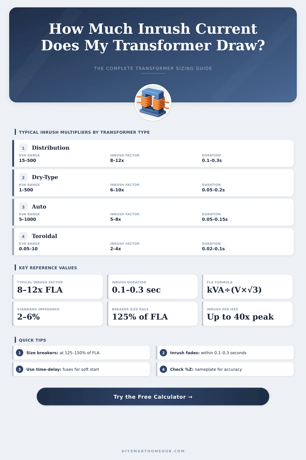
What most grabs the attention of folks is the strength of this. One sees currents that can reach between 10 and 20 times more than the normal flow during use. Truly a lot of extra electricity runs through your setup.
Transformer Start-Up Surge and How to Reduce It
Why does this happen? The cause lies in the process of magnetizing the core. When you for the first time turn on the Transformer, the magnetic core needs time to settle and reach a steady current level.
If there is already magnetism in the core, or if the switching of energy happens exactly at a voltage peak, those Inrush Current spikes become very strong. Here is the main point: one cannot perdict the exact moment of switching, what causes big differences between one switching and the next.
It is possible to name three main kinds of Inrush Current. The power startup current hits when the voltage reaches the Transformer from outside. There also exists the restart current, that appears after a pause.
The third kind is the packed current. Between them, the power startup current gets the most attention in the scientific writing.
The patterns that appear show that the size of the Inrush Current ranges between 7 and 12 times the rated capacity of the Transformer. One can also find it listed as 3 to 14 times the full load amps; it depends on the reference. The length usually is short, around 0.1 seconds, although in special cases it stretches to a whole second.
Here is where it gets interesting: big Transformers with low resistance in the coils and high inductance can experience such currents four some seconds, before the spike goes away. Generally, bigger devices cause stronger surges.
That happens regardless of whether something connects to the secondary side. As soon as the core reaches saturation, the inductance of the coils quickly drops. In that moment, only the resistance of the primary coil and the impedance of the power line stay to limit the flow.
Because the saturation happens only during part of the half cycles, the result is waveforms full of harmonics. That rich in harmonics mess can create trouble in nearby devices, causing noise and dirt in the whole grid.
The results of high Inrush Current range from blown fuses and tripped breakers to whole system failures. Toroidal Transformers are known for blowing fuses during startup. One fix is to use serial resistance for the Transformer, that limits the flow quite a lot to avoid tripping of breakers.
Another method is made up of stepped switching of the Transformer by means of controlled switching, a soft starter or phase angle control works well for that. They smooth the change of voltage and limit the strength of the Inrush Current. The good newsis that the worst case almost never happens in practice.