⚡ Transformer Turns Ratio Calculator
Calculate primary & secondary turns, voltages, currents, and impedance ratios for any transformer
| Application | Primary V | Secondary V | Turns Ratio (a) | Type |
|---|---|---|---|---|
| Doorbell Transformer | 120 V | 16 V | 7.5:1 | Step-Down |
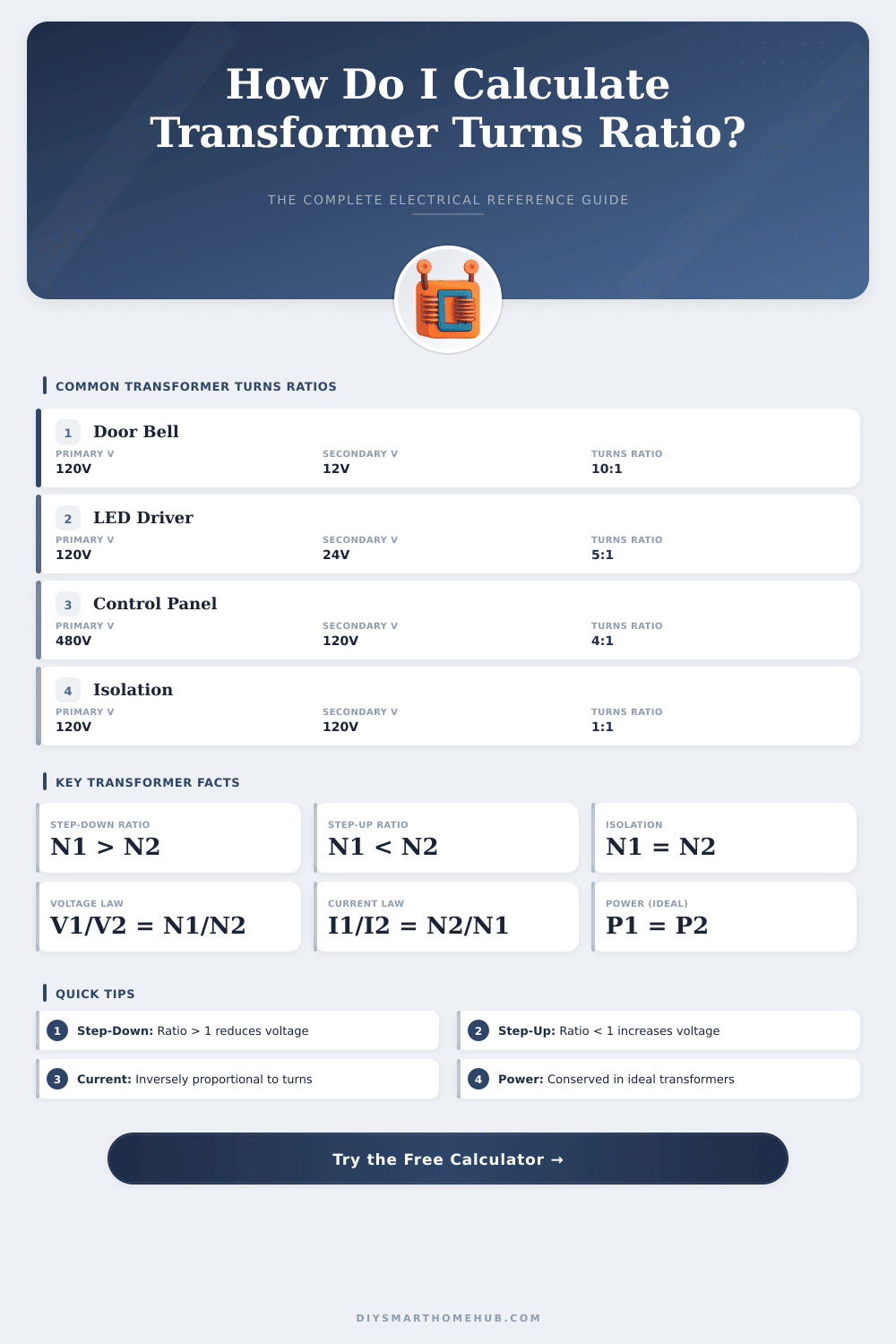
| Control Panel | 480 V | 120 V | 4:1 | Step-Down |
| LED Driver | 120 V | 24 V | 5:1 | Step-Down |
| Distribution Transformer | 11,000 V | 415 V | 26.5:1 | Step-Down |
| Neon Sign Transformer | 120 V | 9,000 V | 1:75 | Step-Up |
| Isolation Transformer | 120 V | 120 V | 1:1 | Isolation |
| Auto Transformer | 240 V | 120 V | 2:1 | Step-Down |
| Microwave Oven HV | 120 V | 2,100 V | 1:17.5 | Step-Up |
| Battery Charger 12V | 120 V | 14.4 V | 8.3:1 | Step-Down |
| Transmission Line | 13,800 V | 138,000 V | 1:10 | Step-Up |
| Turns Ratio (a) | Impedance Ratio (a²) | Voltage Ratio | Current Ratio |
|---|---|---|---|
| 1:1 | 1:1 | 1:1 | 1:1 |
| 2:1 | 4:1 | 2:1 | 1:2 |
| 4:1 | 16:1 | 4:1 | 1:4 |
| 5:1 | 25:1 | 5:1 | 1:5 |
| 10:1 | 100:1 | 10:1 | 1:10 |
| 20:1 | 400:1 | 20:1 | 1:20 |
| 1:2 | 1:4 | 1:2 | 2:1 |
| 1:10 | 1:100 | 1:10 | 10:1 |
| CT Ratio | Primary Current | Secondary Current | Typical Use |
|---|---|---|---|
| 100:5 | 100 A | 5 A | Metering / Protection |
| 200:5 | 200 A | 5 A | Feeder Protection |
| 400:5 | 400 A | 5 A | Bus Bar Metering |
| 600:5 | 600 A | 5 A | MV Panel Metering |
| 1000:5 | 1,000 A | 5 A | Substation CT |
| 2000:5 | 2,000 A | 5 A | HV Transmission |
| 3000:1 | 3,000 A | 1 A | Revenue Metering |
The turn ratio of a Transformer is the relation between the number of turns in the primary winding and that in the secondary winding. One shows it by means of two numbers for instance 2:1 or simply 2 against 1. The first number relates to the turns of the primary side, the second to those of the secondary.
Transformer is made up of two windings wrapped around a magnetic core, called the primary and the secondary. Those windings stay electrically insulated one from the other.
What is the Turn Ratio of a Transformer
The ratio of voltages between the primary and secondary winding is set by that turn ratio. Transformer does not create new energy. It simply adjusts the voltage according to the amount of turns.
According to Faraday’s law, the voltage in a winding is tied to its number of turns. Like this, the ratios of voltages in the windings match the turn ratio.
To find the turn ratio, one divides the primary voltage by the secondary. For instance, 30 kV is divided by 400 V to get the value. Consider that: if the input voltage sits around 300 V and the output 15 V, then the turn ratio reaches around 20:1.
Or assume that the primary side requires 120 V and teh output is 12 V. This results in a 10:1 ratio. Transformer with 500 turns in the primary and 1000 in the secondary has a 1:2 ratio.
In a perfect Transformer, one finds the turn ratio by means of the real output voltage on one winding, while one applies a known real input voltage at the right frequency to the other. In a balanced setup, where the core is equal and both windings have the same number of turns as well as wire thickness, the input and output wood match one the other.
It is also possible to relate the turn ratio and impedance. The impedance ratio matches the square of the turn. Otherwise said, the turn ratio is the square root of the impedance.
Without taking apart the Transformer, this method allows one to count the reflected impedance.
When a Transformer is already built, its turn ratio cannot be changed except by destroying it and redoing the windings. Running it at a different frequency will not affect the ratio. In actual Transformers, the amount of turns in primary and secondary carefully balance between losses in the core, copper losses, working frequency and overall size.
A high turn ratio can mean slightly lower efficiency. The test of Transformer turn ratio ranks among the most used to check the state of windings and core in aTransformer.
Current sensor Transformers differ a bit. Their turn ratio does not show the same input-output ratio as power Transformers. They convert current into voltage instead of voltage into voltage.
A 10:1 current sensor Transformer does not mean that 10 amps always give 1 volt.