⚡ Current Transformer Ratio Calculator
Calculate CT ratio, secondary current, turns ratio, and burden — for metering and protection applications
±0.1% error
±0.3% error
±1.0% error
±3.0% error
Most Common
Long Leads
Relay Circuits
Ratio Tolerance
| CT Ratio | Primary (A) | Secondary (A) | Turns Ratio | Typical Application | Accuracy Class |
|---|---|---|---|---|---|
| 50:5 | 50 | 5 | 10:1 | Small residential panel | 0.3 |
| 100:5 | 100 | 5 | 20:1 | 100A residential service | 0.3 |
| 150:5 | 150 | 5 | 30:1 | Small commercial | 0.5 |
| 200:5 | 200 | 5 | 40:1 | 200A commercial service | 0.5 |
| 400:5 | 400 | 5 | 80:1 | 400A panel board | 1.0 |
| 600:5 | 600 | 5 | 120:1 | Distribution feeder | 1.0 |
| 800:5 | 800 | 5 | 160:1 | Large motor / MCC | 1.0 |
| 1000:5 | 1000 | 5 | 200:1 | Industrial switchgear | 3.0 |
| 1500:5 | 1500 | 5 | 300:1 | Substation feeder | 3.0 |
| 2000:5 | 2000 | 5 | 400:1 | HV substation bus | 3.0 |
| 3000:5 | 3000 | 5 | 600:1 | Transmission grid | 3.0 |
| 50:1 | 50 | 1 | 50:1 | Revenue meter, long leads | 0.1 |
| 100:1 | 100 | 1 | 100:1 | Precision revenue billing | 0.2 |
| 200:1 | 200 | 1 | 200:1 | Utility revenue metering | 0.2 |
| Burden (VA) | At 5A — Impedance (Ω) | At 1A — Impedance (Ω) | Typical Use |
|---|---|---|---|
| 2.5 VA | 0.1 Ω | 2.5 Ω | Solid state relay |
| 5.0 VA | 0.2 Ω | 5.0 Ω | Electronic meter |
| 7.5 VA | 0.3 Ω | 7.5 Ω | Ammeter + wiring |
| 12.5 VA | 0.5 Ω | 12.5 Ω | Standard metering circuit |
| 15 VA | 0.6 Ω | 15.0 Ω | Induction relay |
| 20 VA | 0.8 Ω | 20.0 Ω | Overcurrent relay |
| 25 VA | 1.0 Ω | 25.0 Ω | Differential protection |
| 30 VA | 1.2 Ω | 30.0 Ω | Distance relay |
| Accuracy Class | Ratio Error (%) | Phase Error (min) | % of Rated Current | Application |
|---|---|---|---|---|
| 0.1 | ±0.1% | ±5 min | 100% | Precision laboratory |
| 0.2 | ±0.2% | ±10 min | 100% | Utility revenue billing |
| 0.2S | ±0.2% | ±10 min | 1–120% | Smart metering |
| 0.5 | ±0.5% | ±30 min | 100% | General revenue metering |
| 0.5S | ±0.5% | ±30 min | 1–120% | Extended range metering |
| 1.0 | ±1.0% | ±60 min | 100% | Industrial metering |
| 3.0 | ±3.0% | N/A | 50–120% | General protection |
| 5.0 | ±5.0% | N/A | 50–120% | Overcurrent protection |
| Installation | Typical Load (A) | Recommended CT | Secondary | Accuracy Class |
|---|---|---|---|---|
| Residential 100A | 60–80A | 100:5 | 5A | 0.5 |
| Residential 200A | 100–150A | 200:5 | 5A | 0.5 |
| Small Office | 150–300A | 400:5 | 5A | 0.5 |
| Commercial Building | 300–600A | 600:5 | 5A | 1.0 |
| Industrial Plant | 500–900A | 1000:5 | 5A | 1.0 |
| Large Industrial | 1000–1800A | 2000:5 | 5A | 3.0 |
| Utility Substation | 1500–2500A | 3000:5 | 5A | 3.0 |
| Revenue Billing | Any | Matched | 1A or 5A | 0.1–0.2 |
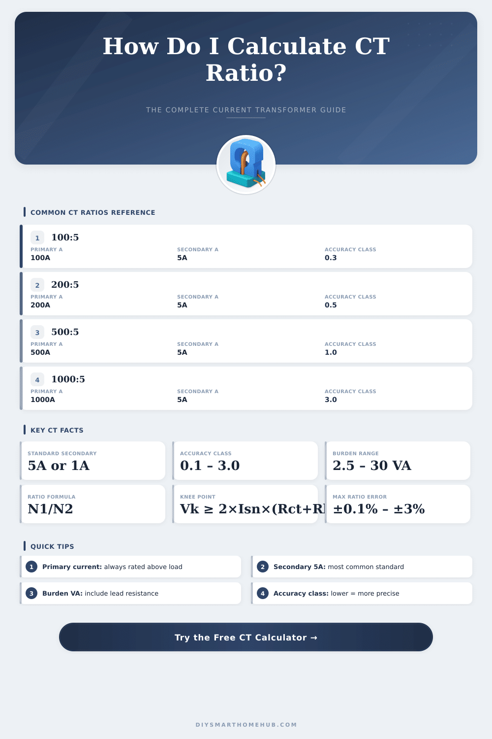
The Current Transformer report forms the main reading, that points, as the CT lowers the basic flow to a much smaller secondary flow. One counts it by sharing the basic flow by the secondary. When one calls the basic flow Ip and the secondary flow Is then the report ratio matches Ip divided by Is.
Like this, CT with rating 100:5 means that the basic flow reaches 100 amps, while the secondary are 5 amps, what gives a report of 20. This element matters a lot for accurate measurement, guard and control of electrical nets.
Current Transformers: What They Do and How to Choose One
The most many Current Transformers own a standard secondary name of 5 amps. One presents the basic and secondary flows as a ratio, for instance 100/5. This shows, that the basic flow beats the secondary by 20 times.
Such Current Transformers work similarly to volt transformers and obey the same main rules. The volt ratio of the Current Transformer matches directly to the current ratio. The winidngs of CT determine its transformer report and its reliability.
Here something notable about windings. CT of 300:5 with one basic spool has 60 secondary spools. They usually wrap with thin cable and hide inside the body of CT.
The label assumes, that the basic conductor passes through the central opening only one time. Even so, if the basic conductor passes twice through the opening, then 100:5 Current Transformer starts to act as 50:5 unit instead.
This reminds of a useful effect. Simple changes of the CT report are possible, if one passes the basic conductor threw the CT many times. For better fit, one can run the secondary conductor through the window of CT added or subtracted.
For instance, four spools could be added to reach 60:5 report in a particular case. Adding or removing secondary spools will alter the report.
During the choice of right CT report, consider the expected current. In a perfect case, the report of CT should beat the expected flow, usually around 120 percent. To find the right Current Transformer name, multiply the maximum load in amps by 1.25.
For instance, if the standard flow is 1 154 amps, then one picks a CT report of 1 250:5.
The report mistakes form another part, that is worth knowing. According to standards of IEEE, the mistake of report reaches 10 percent. The IEC standard offers grades of 5 and 10 percent, where 5 percent are better.
The current limit in IEEE standard matches 20 times the basic current name of CT, and 20 times are also the lead limit in IEC. Choose the right report to escape wrong saturation of CT during faults, what allows, that protective relay devices receive reliablecurrent signs.
Current Transformers create alternating flow in the secondary spool, that matches the flow, that one measures in the basic. They lower high flows to much lower levels. The losses in lines for 1-amp Current Transformers are only 4 percent compared to 5-amp units, although devices for 1-amp secondaries commonly show a bit less precise measure.