📡 Quarter Wave Transformer Calculator
Calculate impedance matching transformer length & characteristic impedance for RF circuits
Solid PE core
Foam PE core
Foam core
εr ~ 4.4
εr ~ 4.4
Waveguide
Cat5e/Cat6
Solid PE
| Frequency | Full λ (mm) | λ/4 (mm) | λ/4 (in) | λ/4 at VF 0.66 (mm) | λ/4 at VF 0.85 (mm) |
|---|---|---|---|---|---|
| 100 MHz | 3,000 | 750 | 29.53 | 495 | 637.5 |
| 433 MHz | 692.4 | 173.1 | 6.81 | 114.2 | 147.1 |
| 868 MHz | 346.2 | 86.5 | 3.41 | 57.1 | 73.6 |
| 915 MHz | 327.9 | 82.0 | 3.23 | 54.1 | 69.7 |
| 1.0 GHz | 300.0 | 75.0 | 2.95 | 49.5 | 63.8 |
| 2.4 GHz | 125.0 | 31.25 | 1.23 | 20.6 | 26.6 |
| 5.8 GHz | 51.7 | 12.93 | 0.509 | 8.53 | 11.0 |
| 10.0 GHz | 30.0 | 7.50 | 0.295 | 4.95 | 6.38 |
| 24.0 GHz | 12.5 | 3.125 | 0.123 | 2.06 | 2.66 |
| Z₁ (Ω) | Z₂ (Ω) | Z₀ = √(Z₁×Z₂) (Ω) | Impedance Ratio | Typical Application |
|---|---|---|---|---|
| 50 | 75 | 61.24 | 1.5:1 | Coax to video/CATV |
| 50 | 100 | 70.71 | 2:1 | Balun matching |
| 50 | 200 | 100.0 | 4:1 | Dipole antenna feed |
| 50 | 300 | 122.47 | 6:1 | Folded dipole |
| 50 | 450 | 150.0 | 9:1 | Open wire feedline |
| 75 | 150 | 106.07 | 2:1 | CATV splitter matching |
| 75 | 300 | 150.0 | 4:1 | UHF/VHF antenna |
| 50 | 50 | 50.0 | 1:1 | No mismatch (reference) |
| SWR | Reflection Coeff. Γ | Return Loss (dB) | Power Reflected (%) | Match Quality |
|---|---|---|---|---|
| 1.0:1 | 0.000 | ∞ | 0% | Perfect match |
| 1.2:1 | 0.091 | 20.8 | 0.83% | Excellent |
| 1.5:1 | 0.200 | 14.0 | 4.0% | Good |
| 2.0:1 | 0.333 | 9.54 | 11.1% | Acceptable |
| 2.5:1 | 0.429 | 7.35 | 18.4% | Marginal |
| 3.0:1 | 0.500 | 6.02 | 25.0% | Poor |
| 5.0:1 | 0.667 | 3.52 | 44.4% | Very poor |
| 10.0:1 | 0.818 | 1.74 | 66.9% | Unacceptable |
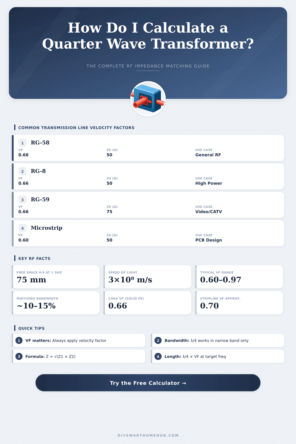
A quarter wave transformer is used as part of a signal line, that is around one quarter of the wavelength of the signal passing through it. In electronics it helps to tie two lines with different impedance. The advantage of it is that it does not need any extras to work.
It uses its wavelength for the matching process, what makes it very practical.
How a Quarter Wave Transformer Matches Two Lines
The basic idea comes from the link between the physical length of a signal line and its electrical wavelength. If a line is exactly a quarter of a wavelength, its impedance goes through a 90-degree phase shift. Here is everything that makes it useable.
How does it then work? One can lay it between a feed line and a load, to match the impedance of the load to the impedance of the line. It forms an easy and practical circuit for matching the impedance at the final load.
When the load has different impedance than the line that feeds it, the quarter wave transformer takes care of the outer issues.
One has a formula to count the right impedance of the quarter wave transformer part. The impedance of that line equals the square root of the product from the two impedances, that one matches. For instance, if one value is 25 ohms and the other 100 ohms, then the line needs impedance equal to the square root of 25 times 100.
That forms an easy calculation.
The input impedance of a quarter wave long signal line, bound to a load, equals the square of the impedance divided by the impedance of the load. Like this a quarter wave long line fits too alter high impedance to low and vice versa.
Things become more interesting, when one combines several quarter wave transformer parts. A design of a multi-section quarter wave transformer uses several sections of signal lines, every one a quarter of a wavelength long at the central frequency. It may seem, that sections of various lengths would give better results, however the idea is based on equal quarter wave transformer sections.
Quarter wave transformers commonly appear in work with microwave frequencies, that start above 600 MHz. They help in applications for antennas. For microstrip patch antennas it matters a lot to count the precise sizes of the quarter wave transformer.
A typical case is matching a 50-ohm signal line to a 100-ohm resistive load by means of a quarter wave transformer section. At lower frequencies on the other hand, using a real signal line for such a goal can be impractical, so sometimes one uses an equivalent lumped circuit version to copy the same behavior.
A half-wave end-fed antenna has very high impedance at its feed point, so one must use a quarter wave transformer to lower that impedance to something that a radio can handle. Quarter wave transformer sections fit to also serve as cheap bandstop filters, to stop RF energy from going back into a preamplifier circuit andinhibit issues below by means of low impedance.