⚡ Transformer Voltage Drop Calculator
Calculate voltage drop across wire runs for transformers — low voltage, line voltage & distribution systems
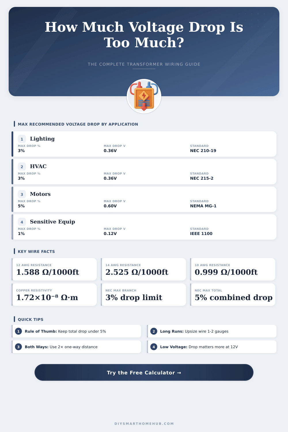
| Application | Max Branch Drop | Max Feeder Drop | Max Total Drop | Standard Reference |
|---|---|---|---|---|
| General Lighting | 3% | 2% | 5% | NEC 210-19(A) |
| HVAC / Heating | 3% | 2% | 5% | NEC 215-2(A) |
| Motor Loads | 5% | 3% | 5% | NEMA MG-1 |
| Sensitive Electronics | 1% | 1% | 2% | IEEE 1100 |
| Distribution Panel | — | 1% | 3% | NEC 215-2(A) |
| Low Voltage (12V) | 3% | 2% | 5% | NEC 411.6 |
| AWG | mm² | Cu Ω/1000ft (20°C) | Al Ω/1000ft (20°C) | Cu Ω/km (20°C) | Max Amps (60°C) |
|---|---|---|---|---|---|
| 18 AWG | 0.82 | 6.385 | 10.470 | 20.94 | 14 A |
| 16 AWG | 1.31 | 4.016 | 6.590 | 13.17 | 18 A |
| 14 AWG | 2.08 | 2.525 | 4.140 | 8.29 | 20 A |
| 12 AWG | 3.31 | 1.588 | 2.603 | 5.21 | 25 A |
| 10 AWG | 5.26 | 0.999 | 1.637 | 3.28 | 35 A |
| 8 AWG | 8.37 | 0.628 | 1.028 | 2.06 | 50 A |
| 6 AWG | 13.30 | 0.395 | 0.647 | 1.30 | 65 A |
| 4 AWG | 21.15 | 0.249 | 0.408 | 0.82 | 85 A |
| 2 AWG | 33.62 | 0.157 | 0.257 | 0.51 | 115 A |
| 1/0 AWG | 53.49 | 0.0983 | 0.161 | 0.32 | 150 A |
| 2/0 AWG | 67.43 | 0.0780 | 0.128 | 0.26 | 175 A |
| 4/0 AWG | 107.2 | 0.0490 | 0.0804 | 0.16 | 230 A |
| Distance (ft) | 14 AWG Drop | 12 AWG Drop | 10 AWG Drop | 8 AWG Drop | Compliant at 3%? |
|---|---|---|---|---|---|
| 25 ft | 0.19V (0.16%) | 0.12V (0.10%) | 0.07V (0.06%) | 0.05V (0.04%) | ✅ All OK |
| 50 ft | 0.38V (0.32%) | 0.24V (0.20%) | 0.15V (0.12%) | 0.09V (0.08%) | ✅ All OK |
| 100 ft | 0.76V (0.63%) | 0.48V (0.40%) | 0.30V (0.25%) | 0.19V (0.16%) | ✅ All OK |
| 150 ft | 1.14V (0.95%) | 0.71V (0.59%) | 0.45V (0.37%) | 0.28V (0.23%) | ✅ All OK |
| 200 ft | 1.52V (1.26%) | 0.95V (0.79%) | 0.60V (0.50%) | 0.38V (0.31%) | ✅ All OK |
| 300 ft | 2.27V (1.89%) | 1.43V (1.19%) | 0.90V (0.75%) | 0.56V (0.47%) | ✅ All OK |
| 400 ft | 3.03V (2.52%) | 1.91V (1.59%) | 1.20V (1.00%) | 0.75V (0.63%) | ✅ All OK |
| 500 ft | 3.79V (3.15%) | 2.38V (1.99%) | 1.50V (1.25%) | 0.94V (0.78%) | ⚠️ 14AWG fails |
| Wire Gauge | Max 12V Run (3% drop) | Max 24V Run (3% drop) | Resistance Ω/1000ft | Typical Application |
|---|---|---|---|---|
| 18 AWG | 9 ft at 10A | 18 ft at 10A | 6.385 | Low-watt fixtures |
| 16 AWG | 14 ft at 10A | 28 ft at 10A | 4.016 | Pathway lights |
| 14 AWG | 22 ft at 10A | 44 ft at 10A | 2.525 | Landscape lighting |
| 12 AWG | 35 ft at 10A | 70 ft at 10A | 1.588 | Longer runs |
| 10 AWG | 56 ft at 10A | 112 ft at 10A | 0.999 | High-load runs |
| 8 AWG | 89 ft at 10A | 178 ft at 10A | 0.628 | Very long runs |
Voltage drop occurs over the entire circuit — both the hot/supply conductor and the neutral/return conductor. Always enter the one-way distance and the calculator multiplies by 2 automatically. For 3-phase systems, the multiplier changes to 1.732 (√3) instead of 2.
A 0.36V drop on a 120V system is only 0.3% — barely noticeable. The same 0.36V drop on a 12V system is 3% — at the NEC limit. Always check percentage drop, not just absolute voltage drop. Upsize wire 1–2 AWG gauges for runs over 100ft on 12V or 24V systems.
transformer voltage drop happens because of changes in the output volt caused by the load bound to the secondary coil. The internal resistance of the coils and the common reactance reports about this drop. In short words when more current is drawn from the transformer, the volt at the output drops.
For single-phase transformer, the formula for voltage drop is Vd match to the current multiplied by the amount of resistance times the cosine of the angle of power factor and reactance times the sine of that angle. Three-phase transformers apply alike equation, but with the square root of three as factor. This computing tool allows to estimate, how many volt miss under various conditions of load.
Why Transformer Output Voltage Drops and How to Check It
Here is something notable about the power factor. If the load has first power factor, the reactive part of the voltage drop almost vanishes. Even so, when the power factor moves toward inductive or capacitive 90 degrees, the volt can quickly rise or drop, because the raectance usually are much more big than the resistance.
Fast mode estimate the voltage drop are control the impedance on the nameplate of the transformer. For instance, if it points 3.0 percent impedance, that wants to say around 3.0 percent loss of volt on the secondary side during full nominal current. Different models of transformers can have different values for voltage drop even at same power factor, and that difference commonly depends on the impedance.
The percent impedance value is identical for both coils, because of what one uses it instead of simple ohm number.
The voltage regulation points, how effectively operates the transformer. Ideal copy would have zero regulation, but in reality always happen a bit of drop. Transformers with low nominal VA commonly delivers 10 until 20 percent more volt when no load is connected.
When one leads the load, the volt then drops.
Change of the load affects the voltage drop. If group of devices turns off, the secondary volt can recover too normal levels. Engineers occasionally settle that by means of change of the taps in the transformer.
For sample, some three-phase models own six taps with 2.5 percent steps, so the output one can adapt for compensate until 5 percent voltage drop on the input side.
For precise calculation of voltage drop, one requires to know the resistance of the primary and secondary coils. Knowing the relation X/R and the power factor of the load also is useful. Putting those data in calculator, one can estimate, do the drop is quite a lot big for affect the system range.
Occasionally one adds in manual computing assumed 3 or 5 percent drop on the primary side above the intended value, only for be safe. In one actual case, the voltage drop grew of around 1.4 percent until 3.8 percent between the bus in front and after the transformer.
Even more little transformers can provide the needed current, but with fewer volt, or give the right volt, but with fewer current. The excessive resistance in the low-volt coils commonly limits, how far indeed onecan draw from them.