High Power LED Driver Calculator
Size a constant-current LED driver from string voltage, array current, supply voltage, driver topology, wattage derating, and junction-temperature thermal limits.
⚡Named LED Driver Presets
🔧LED Array And Driver Inputs
🌡Thermal Model Inputs
📊Selected Package Spec Snapshot
🔍LED Package Reference Table
| LED Type | Typical Vf | Nominal Current | Power Range | Thermal Note |
|---|---|---|---|---|
| 1 W discrete emitter | 3.0-3.4 V | 300-350 mA | 0.9-1.2 W each | Small star board usually needs airflow |
| 3 W discrete emitter | 3.0-3.6 V | 600-700 mA | 1.8-2.5 W each | Check junction-to-case resistance closely |
| 10 W COB module | 9-12 V | 700-1050 mA | 7-12 W module | Interface resistance matters more than wiring |
| 30 W COB module | 30-38 V | 700-1000 mA | 22-38 W module | Use heatsink Rth from measured conditions |
| Royal blue high-power LED | 3.1-3.8 V | 700-1500 mA | 2.2-5.7 W each | Vf bins vary strongly by current and heat |
| 365 nm UV emitter | 3.4-4.2 V | 500-1000 mA | 1.7-4.2 W each | Thermal and optical aging limits are strict |
⚙Driver Topology Comparison Grid
| Topology | Use When | Key Formula Check | Typical Efficiency | Design Watchpoint |
|---|---|---|---|---|
| Buck constant-current | Supply is above LED string voltage | Supply > Vstring max + overhead | 88-95% | High duty cycle can lose regulation |
| Boost constant-current | Supply is below LED string voltage | Input current = Pin / Vin | 85-93% | Switch current rises at low supply voltage |
| Buck-boost constant-current | Supply can cross LED string voltage | Output may be above or below input | 82-92% | More switching stress than buck alone |
| Linear constant-current | Small voltage drop and low current | Heat = (Vin - Vstring) x I | Depends on voltage drop | Driver heat can exceed LED heat quickly |
🌡Thermal Target Reference
| Junction Result | Meaning | Action |
|---|---|---|
| < 75°C | Conservative | Usually good margin |
| 75-90°C | Normal power LED range | Check enclosure temperature |
| 90-105°C | Warm but common | Derate current or improve heatsink |
| > 105°C | High stress | Use lower current or lower Rth |
| Thermal Part | Typical Range | Calculator Input |
|---|---|---|
| Junction-to-case | 0.8-12°C/W | LED Rth J-C |
| Interface pad or paste | 0.1-2°C/W | Case-to-sink Rth |
| Small passive sink | 8-25°C/W | Heatsink-to-air Rth |
| Large finned sink | 0.5-6°C/W | Heatsink-to-air Rth |
📋Common High-Power LED Project Sizes
| Project | Typical Array | Driver Output | Supply Range | Thermal Focus |
|---|---|---|---|---|
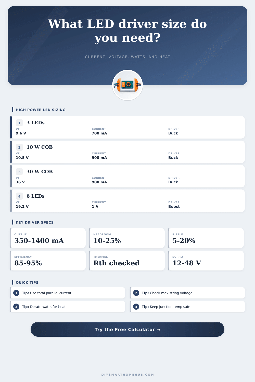
| Desk task spotlight | 3 x 3 W LEDs | 9-11 V, 700 mA | 12-15 V buck | Small star-board heatsink |
| Under-cabinet bar | 6 x 3 W LEDs | 18-22 V, 700 mA | 24 V buck | Aluminum channel temperature |
| 30 W COB downlight | 1 COB module | 30-38 V, 900 mA | 48 V buck | COB case-to-sink interface |
| Battery boost lantern | 6 white LEDs | 18-21 V, 1 A | 9-12 V boost | Input current and switch heat |
| UV curing head | 8S2P UV LEDs | 27-34 V, 1.4 A | 36-48 V buck | Junction temp and UV aging |
💡Driver Sizing Tip Boxes
LEDs are cool technology but most projects don’t make it past installation. A few weeks in everything is great until it starts going yellow, gets dimmer and eventualy… the diode bites the dust. No need to blame yourself and change light source. Your choice of fixture was fine. What went wrong? You didn’t account for heat generated by high power LEDs.
They convert electrons to photons with great efficiency. However, all those watts also becomes waste heat that has no place to go. Until you provide a thermal pathway for that waste heat move from the chip to surrounding air, your brightness goals is only theoretical. It forces you to consider how whatever you choose will affect your LEDs’ temperature, and it does electrical sizing for you too.
Why Your LEDs Fail Because of Heat
Matching current and voltage isn’t everything, but it’s part of it. More importantly, you should understands that for every watt you put in LED array, some number of watts come back out as light and some as heat. Usually, most of them is heat. Put in your drive current and forward voltage and it will estimate the total power draw. It is really valuable because of what it does with remainder of that energy. How many watts of the switching driver are dissipated internally as its own kind of friction (separate from heat that radiates from the LED package)? Everything about how efficient and stressful this will be depend on choosing right driver topology.
Do you have an available supply voltage higher than your desired LED string voltage? Use a buck converter. Are you using a solar panel or other source that dips below required voltage for your LEDs? You want a boost topology to lift that voltage back up. The calculator shows this tradeoff by helping you estimate the input demand with each topology along with expected loss in the driver itself.
It may seem tempting to try a linear regulator since there aren’t many parts, but it burns off all that excess voltage as pure heat. Before you get close to your target lumen output, that additional heat can exceed capacity of your heatsink. That’s where most people end up learning hard way when their enclosure becomes a hot water bottle.
Good designs last, junk gets tossed out. Thermal modeling helps separate them. Instead of thinking about heat dissipation in terms off “a sink,” consider it instead as series of resistances. The calculator breaks that down into three parts: junction-to-case resistance, then the interface material between heatsink and the LED, followed by ability of the heatsink itself to reject heat to surrounding air.
While many designer gets caught up in buying a bigger array of aluminum fins, they ignore the sandwich of thermal paste or a pad in the middle. No matter how big the fin array, a thin layer of dried thermal compound is going to act as an insulator, trapping heat at the junction. To help show that, the tool lets you adjust the interface resistances to see how much your real-world junction temperature rise above the ambient room temperature.
The other quiet killer of LED arrays are forward voltage variation. Even LEDs from the same batch are not all created equal. Some will have a slightly higher forward voltage than others. If you don’t account for this variation and wire them together in parallel, the lower voltage LEDs will hog more current, run hotter, and fail first. You can specify the allowance on high-bins voltage. You can also decide how to manage multiple string in parallel with the driver. This allows you to size up the driver so it can handles the manufacturing tolerance. It forces you to think about whether your supply has enough headroom to handle the worst case, not just the average case.
Lighting design is a trade-off between optimal performance and long-term reliability. Pushing more amperes through an LED makes it shine more brightly today, but that comes at the cost of higher operating temperatures that lead to shorter lifetime and faster degradation. When the datasheet lacks details (or is lacking), the built-in reference tables contains typical values for popular discrete emitters and COB modules. These will help you get started.
Once you have the preset values, tweak the thermal resistances until the calculated junction temp lands squarely within your comfortabley zone, well before reaching your safety threshold. Shorter term, a colder LED emits less light. Longer term, though, its color stays more consistent. It also outlasts hotter-running LEDs by quite some time. Thinking ahead about heat would of spared you from running after dead diodes down the road.