LED Driver Circuit Calculator
Compare resistor, linear, buck, boost, and regulated constant-current driver choices using LED string voltage, target current, ripple allowance, headroom, efficiency, and thermal derating.
| Topology | Voltage rule | Sizing formula | Best circuit use |
|---|---|---|---|
| Series resistor | Supply above LED string | R = (Vin - Vf string) / I | Indicators, tiny arrays, fixed supply |
| Linear current regulator | Vin at least string plus dropout | Loss = (Vin - Vstring) x I total | Low-noise dimming and short strings |
| Buck current driver | Vin higher than string voltage | Pin = Pled / efficiency | 12 V or 24 V supply to fewer series LEDs |
| Boost current driver | Vin lower than string voltage | Iin = Pled / (Vin x efficiency) | Battery supply into longer LED strings |
| LED type | Typical Vf | Common current | Driver note |
|---|---|---|---|
| Red status LED | 1.8-2.2 V | 2-20 mA | Resistor sizing is often adequate |
| White indicator LED | 2.8-3.4 V | 5-30 mA | Check low-supply headroom |
| IR emitter | 1.2-1.6 V | 20-1000 mA | Pulse current needs extra thermal margin |
| Small lighting LED | 2.7-3.3 V | 60-350 mA | Constant-current switching is preferred |
| Ripple target | Current waveform | Component impact | Use case |
|---|---|---|---|
| 5-10% | Very smooth | Larger inductor or capacitor | Cameras, optical sensing, dim video scenes |
| 15-25% | Moderate ripple | Balanced magnetic size | Cabinet strips and accent lighting |
| 30-35% | Compact driver | Smaller inductor, more peak current | General indicators and noncritical loads |
| 40-50% | High ripple | Smallest parts, highest stress | Only when LED and EMI limits allow it |
| Derating | Meaning | Thermal result | Design note |
|---|---|---|---|
| 100% | Nameplate rating | Hottest operation | Use only with verified cooling |
| 80% | Light margin | Warmer small enclosure | Common for ventilated electronics |
| 70% | Moderate margin | Lower part temperature | Good default for enclosed hubs |
| 50% | Conservative margin | Coolest component choice | Useful near batteries or plastics |
But then you meet LEDs which are unlike regular lightbulbs. LEDs don’t just passively sit there waiting to be powered. They draws a certain amount of current and if you don’t give them what they want, they’ll burn out, or at least dim out. A tiny keychain is fine with a little resistor, but when you’re powering big strip in a cabinet off your wall adapter, you have problems.
The supply voltage varys. The LED forward voltage varies with temperature. Now, your simple circuit are a crapshoot between working, being completely dark, or both. The correct driver for your application can depends on how well the LED string matches your supply voltage and power source.
How to Pick the Right LED Driver
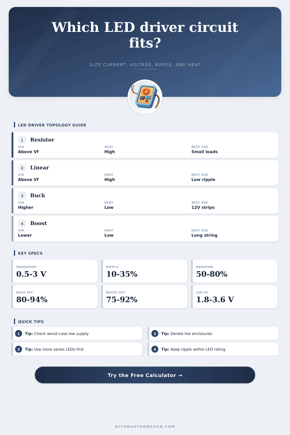
A buck converter (stepping the voltage down efficienty while regulating current) makes sense if you have a significantly higher supply voltage than the total forward voltage of the LED string. But a boost driver will raises the voltage if your LED chain requires more voltage then your supply provides or if the battery is dropping out. The calculator verifies that the topology you select has adequate voltage margins based off what you have available. Otherwise, it won’t matter how efficient your choice of components may be, if the input voltage is too low, a buck converter will of be a waste of money in any case.
Heat is a silent killer in LED driver design and can causes failure. People tend to look at the percentage of efficiency without looking at what that inefficiency actualy does. With resistors and linear regulators, all of that inefficient voltage become waste heat within your enclosure. To determine the thermal load, multiply current times the voltage drop. This means small drops with low current result in no noticeable warmth. Big drops with high current creates lots of warmth in a confined area. Consequently, you has to derate components for this. Using parts rated at their max will cause them to fail if the ambient temperature rise or your venting is blocked by dust.
Another newbie faces a dilemma called ripple from ripple. While switching drivers are efficient, they also inject unwanted artifacts into the output waveform. To our camera sensors, ripple looks like shimmer; to our eyes it feel like flickering. Bigger components will minimizes ripple. Increasing the size of capacitor or inductor tames voltage spikes and decreases ripple as a % of the output. As the reference table indicates, tolerating 30% ripple demands smaller parts then maintaining 10% ripple does. A moderate amount of ripple is fine or unnoticeable when used for basic illumination. When you’re working with video, that ripple distracts. And removing it after the fact are difficult.
More important than you’d think is forward voltage tolerance. Within a given batch of LEDs, the forward voltage can differs. When designed to the average, some of the strings pulls a little more current; some pull a little less. Because hotter LEDs pull a little more, they creates thermal runaway… Which means that the hot ones gets even hotter, pulling even more, failing quicker. By designing to the highest possible LED voltage and the lowest supply voltage, you’ll protect yourself from this sort of drift as conditions change or parts age, keeping your circuit stable.
Don’t think you can ignore ripple when there’s video gear in the room, or temperature rise in a sealed box. Before you even get out the soldering iron the tools allow you to visualize those trade-offs. Choose the right topology for your voltage reality, size your strings appropriately and you go from guessing to engineering. Because the circuit takes into account the limits on its components, the light remains steady.