Ceiling Speaker Spacing Calculator
Estimate listener-plane coverage diameter, overlap-adjusted spacing, speaker quantity, and stereo pair placement from room dimensions, ceiling height, and speaker dispersion.
🎯Room and Listening Presets
📐Speaker Layout Inputs
🔍Live Layout Specs
One speaker cell based on spacing squared.
Columns follow the long room dimension.
Use as a starting point before joist checks.
Pair-based layouts round to even counts.
⚖Placement Comparison Grid
Focused music
- Overlap65%
- Angle60-80°
- CountHigher
- UseSeating
Balanced rooms
- Overlap75%
- Angle80-100°
- CountModerate
- UseLiving
Ambient audio
- Overlap85%
- Angle90-110°
- CountLower
- UseKitchen
Voice zones
- Overlap95%
- Angle100-120°
- CountLight
- UsePaging
📊Reference Tables
Coverage diameter from height and dispersion
| Height drop | 60° speaker | 90° speaker | 110° speaker |
|---|---|---|---|
| 4 ft / 1.2 m | 4.6 ft / 1.4 m | 8.0 ft / 2.4 m | 11.4 ft / 3.5 m |
| 5 ft / 1.5 m | 5.8 ft / 1.8 m | 10.0 ft / 3.0 m | 14.3 ft / 4.4 m |
| 6 ft / 1.8 m | 6.9 ft / 2.1 m | 12.0 ft / 3.7 m | 17.1 ft / 5.2 m |
| 8 ft / 2.4 m | 9.2 ft / 2.8 m | 16.0 ft / 4.9 m | 22.9 ft / 7.0 m |
Overlap factor guide
| Overlap setting | Factor | Effect on spacing | Best fit |
|---|---|---|---|
| Tight overlap | 0.65 | Shorter spacing | Music seats, theater height channels |
| Balanced | 0.75 | Moderate spacing | Living rooms and kitchens |
| Light overlap | 0.85 | Wider spacing | Ambient audio across open plans |
| Edge-to-edge | 0.95 | Maximum spacing | Voice-first or light background zones |
Common room planning examples
| Room type | Typical area | Layout target | Placement note |
|---|---|---|---|
| Bedroom | 140-180 sq ft / 13-17 sq m | 2 speakers | Use a centered stereo pair. |
| Kitchen | 180-260 sq ft / 17-24 sq m | 2-4 speakers | Aim coverage at work zones. |
| Living room | 220-360 sq ft / 20-33 sq m | 4-6 speakers | Balance seating and walkway coverage. |
| Open plan | 500-900 sq ft / 46-84 sq m | 6-10 speakers | Split into repeated speaker cells. |
Stereo pair placement checks
| Main seat distance | 60° triangle split | Wall setback floor | Symmetry check |
|---|---|---|---|
| 6 ft / 1.8 m | 5.2 ft / 1.6 m | 2-3 ft / 0.6-0.9 m | Equal distance to seat. |
| 8 ft / 2.4 m | 6.9 ft / 2.1 m | 3-4 ft / 0.9-1.2 m | Keep left and right balanced. |
| 10 ft / 3.0 m | 8.7 ft / 2.6 m | 4-5 ft / 1.2-1.5 m | Avoid crowding side walls. |
| 12 ft / 3.7 m | 10.4 ft / 3.2 m | 5-6 ft / 1.5-1.8 m | Use two pairs for wide seating. |
💡Placement Tips
Ceiling speaker dispersion is most useful where ears actually are. A 9 ft ceiling with seated listeners has a 5 to 6 ft throw, not a 9 ft throw.
After the calculator estimates a count, shift speaker positions around joists, lights, fans, and HVAC registers while keeping the same spacing range and stereo symmetry.
When you buy ceiling speaker, what do you want? You want audio to appear to come from nowhere, and everywhere. And for that reason you want it to be invisable. Achieving this invisible sound field takes more than gut feeling, it takes geometry.
Placing driver too close together creates a harsh specific hotspot that spoils the blend; placing them too far apart create dead zones where music simply drops out entirely. It’s usually the former that determines whether an installation is professional or a messy DIY job: Does the spacing match the dimension of the room? Instead, visualize the concept of sound as coming from cones instead of squares.
How to Place Ceiling Speakers Correctly
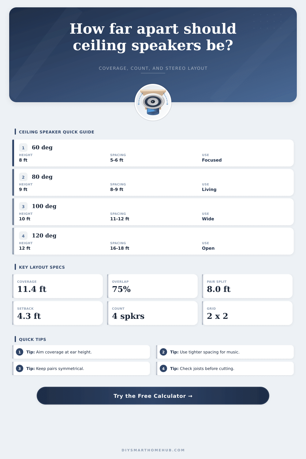
At ear level, a speaker mounted on ceiling projects sound forward in one direction with a certain angle. This creates a cone of sound at ear level. The calculator will do math for you, based off both the room size and the dispersion spec. So now you don’t have to guess where all those invisible cones terminate. It also accounts for listener’s height because that’s where the music has to reach.
Sitting on couch doesn’t make your ceiling nine feet tall (so if you’re sitting down), you want to know what the speaker throw distance is to your ears, not the floor. That change the size of coverage area significantly. If you don’t consider this, speakers will sound thinned-out toward center of the room. The key here is overlap factor, and this is where you need to pay attention.
It measures how far over each speaker’s soundfield should of extend into the next. More overlap result in a seamless blend from speaker to speaker, but requires more total speaker. Less overlap will save you money (since you need less hardware), but may result in holes in your audio blanket. Wherever you value sound quality above all else, such as a home theater or living room, bump up the overlap. When you do so, spacing recommendation will decrease to match, showing that you need less distance for overlap. What you’re doing is purchasing redundancy, which ensure consistency.
For non-critical spaces (hallways, kitchens, etc.), you can loosen those reins a bit. Here, you simply want to fill the space rather than achieve the illusion of perfect sound placement. It’s all about the dispersion angle. For example, you’ll see a speaker marked as 120 degrees, which means it covers more area then a 90 degree speaker at the same height. Folks tend to pick up driver with most watts rated for it, but what good are watts if they don’t disperse them evenly throughout your floor plan?
The table on page references this, breaking down what you should expect from your room size and ceiling drop in terms of how far that sound will spread. More isn’t better… Wider is better. Background music is one thing, but stereo imaging are another. There should be predictability in how the sound arrives from left and right, and it must be symmetrical.
The tool use your main listening seat as starting point and will compute a pair separation distance that gives you clear sound stage instead of two disjointed sources vying for attention. If you’re creating a whole-home system, think of each room as separate zone with unique geometry rules. Don’t attempt to make a single spacing pattern fit a home with widely varied furnitures layout and ceiling height. Nothing ever goes perfectly in the grid because of physical barriers.
You can cut drywall with ease. HVAC ducts, wiring, and joists is another story. What the calculator provides is your best map. Now you must adjust that map to fit real world. Adjust placement up or down by inches to avoid hitting structural items but maintain general placement within a similar range. If a speaker aligns with a beam but is 6 inches over or under, move it there. Don’t do this though if it’s 6 feet away because it “looks” better on paper, maintain symmetry.
Mark all cuts after confirming joist direction first. A mis-cut is costly and once you cut through gypsum board, there’s no going back. Even though the math might not be exact, final layout should feel balanced. Visual imbalance is much more noticeable different than a small difference in sound levels. Make sure you end up with something that looks like an intentional pattern instead of one that’s clearly a grab-bag.
Begin with the middle of space and then adjust to the real world as you progress. If it’s done correctly, you shouldn’t notice the speakers at all. Instead, just listen to music fill the air as it should, when geometry plays into your favor.