Voltage Drop by Wire Run Calculator
Check one-way run length, load current, conductor material, AWG or kcmil size, source voltage, and circuit type to estimate voltage drop, percent loss, delivered voltage, and wire size needed for a target drop.
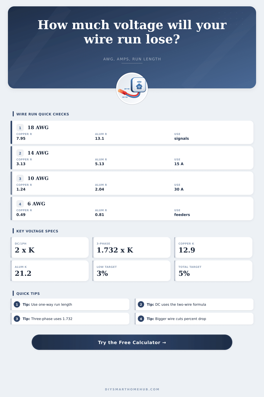
Two-wire circuits use Vdrop = 2 x K x I x D / cmils, where D is one-way feet.
Balanced three-phase circuits use Vdrop = 1.732 x K x I x D / cmils.
One conductor resistance is R/1000 ft = K x 1000 / cmils before parallel adjustment.
Percent drop equals voltage drop divided by source voltage, then multiplied by 100.
| Wire size | cmils | Ohms/1000 ft | Good for |
|---|---|---|---|
| 18 AWG | 1,620 | 7.963 | low current controls |
| 16 AWG | 2,580 | 5.000 | thermostat and signal power |
| 14 AWG | 4,110 | 3.139 | short 120 V branches |
| 12 AWG | 6,530 | 1.975 | longer branch circuits |
| 10 AWG | 10,380 | 1.243 | 30 A class runs |
| 8 AWG | 16,510 | 0.781 | feeders and low voltage loads |
| 6 AWG | 26,240 | 0.492 | higher current feeders |
| 4 AWG | 41,740 | 0.309 | long feeder runs |
| Wire size | cmils | Ohms/1000 ft | Good for |
|---|---|---|---|
| 6 AWG | 26,240 | 0.808 | short feeder checks |
| 4 AWG | 41,740 | 0.508 | moderate feeders |
| 2 AWG | 66,360 | 0.319 | larger feeders |
| 1/0 AWG | 105,600 | 0.201 | service-style conductors |
| 2/0 AWG | 133,100 | 0.159 | long high-current runs |
| 4/0 AWG | 211,600 | 0.100 | large feeders |
| 350 kcmil | 350,000 | 0.061 | very large conductors |
| 500 kcmil | 500,000 | 0.042 | low-drop service runs |
| Run type | Typical voltage | Current range | Drop concern |
|---|---|---|---|
| Video doorbell transformer run | 16 to 24 V | 0.5 to 2 A | Low voltage makes percent drop climb quickly. |
| LED strip or cabinet lighting | 12 or 24 V | 2 to 8 A | Brightness may fade at the far end. |
| Thermostat and sensor power | 24 V | 0.1 to 1 A | Small wire is usually fine until runs get long. |
| 120 V smart branch circuit | 120 V | 2 to 12 A | Percent drop is lower, but watts lost still matter. |
| 240 V garage or hub feeder | 240 V | 15 to 60 A | Long feeders need larger conductors for target drop. |
| Three-phase equipment feed | 208 or 480 V | 5 to 80 A | Use the 1.732 multiplier for balanced loads. |
When your video doorbell turns dark or your smart lock opens by itself, it’s typically not due to firmware bugs or Wi-Fi issues, it’s likely a wiring issue on inside of your walls. Just like water travels down a hose, electricity pass through the wires in your walls. That voltage decreases as it meets resistance within that wire. Thinner and longer wires causes a greater drop in voltage, which can lead to flickering lights or outlets that do not work.
Although the math may be tedious, physics of voltage drop are simple. Resistance exist in every foot of conductor. Thicker wires has less resistance than thinner ones. Longer runs have more resistance then shorter ones. The formula to calculate drop is simply (current draw x total round trip length) divided by the cross-sectional area. Because there are certain constants involved, accurate decimal placement and a bit of math make this difficult to do manually. Once you plug in details about your run, however, a calculator can handles all that for you. It will convert those inputs to percent loss and delivered voltage, which lets you know precisely how much power makes its way to the end of the line.
Why Voltage Drop Happens in Your Wires
Most folks overestimate how much wire they need. They assume the wire run is equal to the “straight line” between the outlet and the panel. But there’s actualy a round-trip distance involved: Electricity needs to flow out to the outlet…then back up to the panel. On a typical two-wire circuit, this happens on the hot wire (down) and then on the neutral wire (back up). So effectively, the wire run is twice as long as the straight-line distance.
That means the measured distance you use in the equation should always be one way; leave it to the equation to double it for you. Otherwise, you’ll estimate half the true run distance, and believe everything is hunky-dory. Only to discover that something downstream don’t have enough juice to work properly.
However, the type of wire used matter. Aluminum weighs less (and is cheaper) than copper, which makes sense given its lower conductivity. So it has more electrical resistance compared to copper. You’ll typically want to bump up to two wire sizes larger if going with aluminum to achieve equivalent performance to copper. In other words, say you have a 10 AWG copper run; you’d replace it with a 6 AWG aluminum run and essentially be reducing the electrical path. This wastes energy, which manifests as heat rather than power.
This is especially true with low voltage systems. On a 120 volt system, a three percent reduction translates into roughly 3.6 volts lost. Appliances rarely notice such a small reduction and operate just fine. However, on a 24 volt doorbell transformer, that same three percent reduction result in only 0.72 volts lost. Such a minor reduction might send sensitive electronics right below their minimum operating point.
Why do security sensors or even landscape lighting frequently require thicker wire than the amperage alone would suggest? You are also battling the resistance of all the wire between the device and its source, not just providing power to it.
Add a third phase, and that changes everything. Current becomes balanced. That’s how it works in industrial applications and some really heavy residential application. Instead of just multiplying by two wires, calculation now uses the square root of three, which is about 1.732. That’s a geometrical gain. Your voltage drop less at the same distance on the same size of wire.
When you’re pulling power to a pool pump or workshop, the right multiplier will keep you from over building the conduit with thicker-than-necessary cable. A little thing, but if the conduit is tight on space, it can make all the difference.
Electrical resistance is also temperature dependent. Conductors increases their resistance as they get warmer. This happens as current flows. This means that a 75 degree C rated conductor will be different than a wire running in your cool basement. If you don’t account for this thermal effect, then you can estimate too optimistically on your wire sizing; only to find out it was wrong when you get an electrical issue on a hot summer afternoon.
Size the wire based off the worst-case scenario for your ambient conditions. You should of paid more for thicker cable initially than have to hunt down electrical issues within your walls once they’re finished.
Voltage drop is that sneaky price you pay on an electrical plan. It’s like a hidden fee that, if ignored, can leave you with dead batteries and dim lights. You want current to get there strong enough to do its job. That means using the right wire length and accounting for losses ahead of time. Use the math to pick your wiring and everything should work correctly from day one.