Short Circuit Forces on Busbars Calculator
Estimate peak electrodynamic force, support reaction, bending stress, and mechanical utilization for low-voltage and medium-voltage busbar runs.
Calculation breakdown
| RMS fault | Peak factor | Peak current | Spacing | Force per metre |
|---|---|---|---|---|
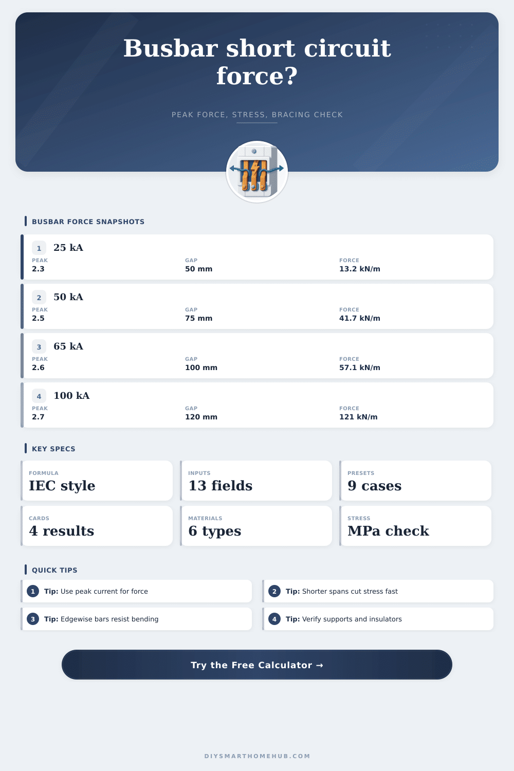
| 25 kA | 2.3 | 57.5 kA | 50 mm | 13.23 kN/m |
| 50 kA | 2.5 | 125 kA | 75 mm | 41.67 kN/m |
| 65 kA | 2.6 | 169 kA | 100 mm | 57.12 kN/m |
| 100 kA | 2.7 | 270 kA | 120 mm | 121.50 kN/m |
| Material | Yield range | Elastic modulus | Conductivity | Mechanical note |
|---|---|---|---|---|
| Hard-drawn copper | 220-280 MPa | 110 GPa | 97-101% IACS | Good stiffness and high current density for compact boards. |
| Annealed copper | 70-100 MPa | 110 GPa | 100% IACS | Lower yield strength; check stress closely on long spans. |
| Aluminum 1350 | 55-95 MPa | 69 GPa | 61-62% IACS | Lightweight, but usually needs larger sections and support care. |
| Aluminum 6101-T6 | 150-190 MPa | 69 GPa | 53-57% IACS | Stronger aluminum option for busway and braced assemblies. |
| Busbar section | Orientation | Approx area | Relative stiffness | Typical use check |
|---|---|---|---|---|
| 25 x 5 mm | Flatwise | 125 mm² | Low | Small panels and protected branch sections. |
| 50 x 10 mm | Flatwise | 500 mm² | Medium | Common LV switchboard bar with close bracing. |
| 80 x 10 mm | Edgewise | 800 mm² | High | Longer spans where bending about the weak axis is avoided. |
| 2 x 100 x 10 mm | Spaced pair | 2000 mm² | Very high | Main sections with high fault level and braced phase packs. |
| Item | Calculator expression | Units | Design meaning |
|---|---|---|---|
| Peak current | Ip = k x Ik | kA peak | Asymmetrical current that produces electrodynamic force. |
| Force per length | F/L = 2 x 10^-7 x Ip^2 / d | N/m | Parallel-conductor magnetic force using metre spacing. |
| Max moment | M = q x L^2 / coefficient | Nmm | Span bending effect from the distributed short-circuit load. |
| Bending stress | Stress = M / section modulus | MPa | Mechanical check against the selected material yield limit. |
In that split second a short circuit occur: Bright. Loud. And violent enough to cause physical damage. You may have heard the report down the hall or seen the arc flash but all too often the damage to your equipment come not from the loud and noisy short circuit but the silent mechanical shock of huge currents traveling through parallel conductor. These current carrying conductors creates magnetic fields that push against each other creating crushing forces of repulsion.
That’s when this calculator comes in handy translating these invisible electromagnetic pulses into actual numbers you can apply to your problem. It calculate the peak electrodynamic force, the support reaction force, and the bending stress. This give you an idea if your busbars bend like a pretzel or hold up just fine to pressure. And the underlying physics is shockingly simple and viciously unforgiving: twice as much current means four times as much repulsive force (because the repulsive force scales with square of the current). So you have to use the worst-case asymmetric current, not just the symmetric RMS value when sizing your support structures.
Why Busbars Bend During Short Circuits
How does it handle this? You feed in the RMS value you expect from your fault. Then the software multiply that by a peak factor. This factor accounts for the asymmetry from the DC offset in the first few cycles of the fault. It is a little thing, but it is the quickest path to designing a bad system that blows up on Day One. Feed in your expected fault level and let the software compute the real peak that will really hit your hardware.
Now we get into geometry, which drives risk once you have the force. It turns out that how close those phases are really matter because magnetic force diminishes when they’re separated. The closer you space them the stronger it gets. Double the gap and you cut the force in half. Unfortunately, most panels is crowded and if you can’t simply move conductors farther apart while still observing clearance rules, you might end up making the switchboard too wide.
You end up focusing on span length instead. The bending moment increase by the square of distance between supports. That’s a pretty steep curve. A 60 cm span produces four times the bending stress of a 30 cm span subjected to the same load. In nearly all cases, a third support is much better than bolting thicker metal onto existing brackets. Just enter that clear mechanical distance and let the calculator do the math for you. This way, you won’t waste time guessing about whether the span width is sufficient.
Another set of compromises that simple electricity equations will not account for are those of materials selection. For example, while copper is a very good conductor with great yield strengths it’s also expensive and heavy. Aluminum is cheaper and lighter, but it has a lower stiffness, so it behaves different when bent. It needs a larger cross section (more wire) to carry the current and experiences different bending stresses. You may find aluminum bars used in industrial feeders where weight is a concern. However, you must take care on long unsupported lines, as the metal bend more under mechanical and repeated thermal stress. The tool allows you to swap from annealed copper to hard drawn copper and several types of aluminum alloys. These materials are then instantly re-calibrated to your selected parameters for stiffness and yield, so you can directly compare different scenarios.
Finally, the last trick everyone forgets until it is too late is orientation. In a flat bar, all of the force is being applied to the wide side. That puts it way off the neutral axis in just one direction. This makes it easy to bend. However, if you mount that bar edge-on, you are placing much more of the material at a distance farther from the centerline of the bend. The section modulus changes immediately and so does the stress calculation. Bending isn’t all about having a lot of copper, but rather where that copper is in relation to the force vector. When you toggle between edgewise and flatwise bending in the input screen, you’ll notice the mechanical use percentage goes through the floor.
In the real world, no system is exactly like the textbook examples you see. Thermal expansion builds up hidden loads over time. Brackets vibrate. Insulators flex. For all of these reasons, the calculator contains a support stiffness factor so you can penalize it if your mounts aren’t rock solid. In the field, conditions are almost never perfect. When in doubt, assume flexible or average support rather than rigid. You wouldn’t want a design that will only survive an ideal test lab environment; you want one that will make it through the messy reality of equipment installation.
There is really no substitute for understanding the physics before cutting the metal and protecting your busbars. In short circuit, the forces are massive and move far quicker then even the best mechanical systems could respond. Planning ahead and looking at bending stress, support loads, and peak force early on will save you much money or worse, a retrofit that never needed to be done. It’s the same principle whether it’s sizing a heavy industrial main or a small service panel. Make your spans short, align your busbars intelligently, and plan for the peak shock not the steady state.