Reactive Power VAR Calculator
Calculate apparent power, real power, reactive power, phase angle, corrected current, and capacitor bank kvar from voltage, current, power factor, phase type, and target power factor.
⚡Reactive Power Presets
🔌Power And Correction Inputs
Reactive power estimate
Calculation breakdown
📊Power Triangle Spec Grid
📋Reactive Power Reference Tables
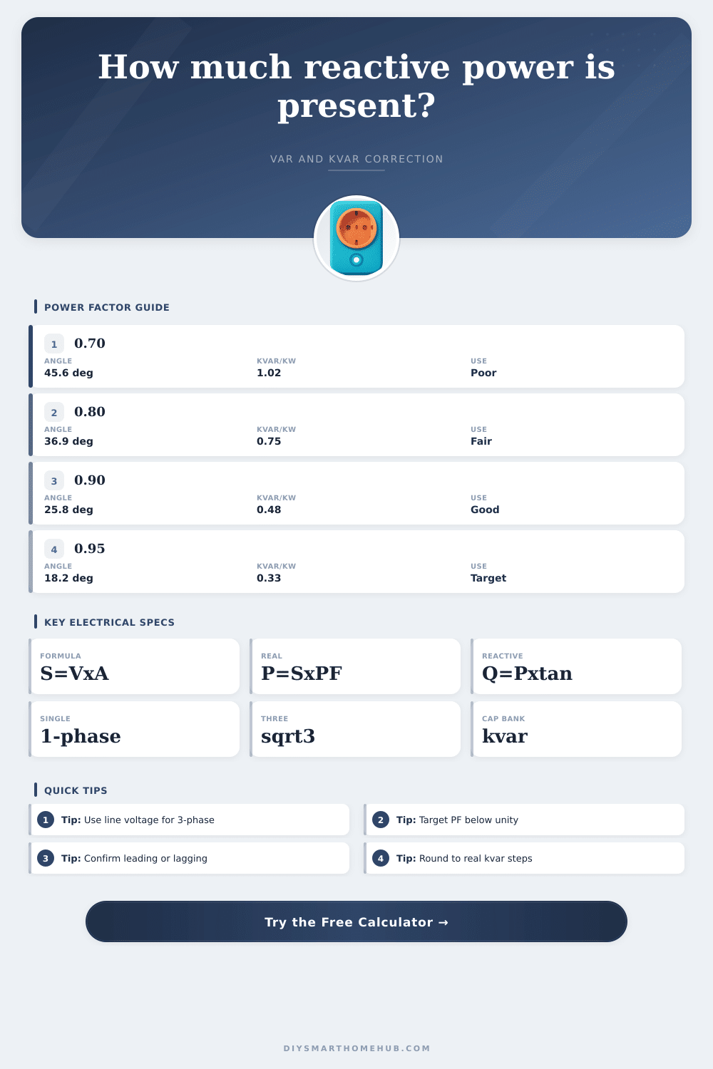
| Power factor | Angle | Reactive kvar per kW | Planning read |
|---|
| Existing PF | Target 0.90 | Target 0.95 | Target 0.98 |
|---|
| Load type | Typical PF | Reactive behavior | Calculator use |
|---|---|---|---|
| Induction motor lightly loaded | 0.55-0.75 | High lagging kvar for the useful kW | Check correction before adding fixed capacitors. |
| Induction motor near rated load | 0.80-0.90 | Moderate lagging kvar | Use measured amps and PF for each operating point. |
| Resistive heating | 0.98-1.00 | Very little reactive power | Correction is usually unnecessary. |
| UPS or switching supply input | 0.70-0.99 | Depends on power factor correction front end | Use the meter PF, not the nameplate alone. |
| Existing capacitor bank | Leading possible | Can over-correct if load drops | Set direction to leading when appropriate. |
| Scenario | Input snapshot | Reactive result | Correction note |
|---|---|---|---|
| 240 V motor branch | 30 A at 0.82 PF | 4.1 kvar lagging | About 2.4 kvar to 0.95 PF. |
| 480 V 3-phase motor | 80 A at 0.78 PF | 41.8 kvar lagging | About 23.4 kvar to 0.95 PF. |
| Server UPS input | 208 V 35 A at 0.95 PF | 2.3 kvar lagging | Small correction to 0.98 PF. |
| Whole home feeder | 240 V 90 A at 0.88 PF | 10.3 kvar lagging | About 5.2 kvar to 0.95 PF. |
🧮Formula Comparison Grid
| Quantity | Single-phase formula | Three-phase formula | Use in calculator |
|---|---|---|---|
| Apparent power S | S = V x A | S = sqrt(3) x VLL x A | Base kVA from voltage and current. |
| Real power P | P = S x PF | P = S x PF | True kW when measured kW is not supplied. |
| Reactive power Q | Q = sqrt(S^2 - P^2) | Q = sqrt(S^2 - P^2) | Cross-check against the power triangle. |
| Reactive power Q | Q = P x tan(acos(PF)) | Q = P x tan(acos(PF)) | Used for target PF capacitor correction. |
| Capacitor correction | Qc = P x (tan old - tan target) | Qc = P x (tan old - tan target) | Required kvar to move from existing PF to target PF. |
🔧Reactive Power Tips
When you use electricity, there’s something called reactive power that’s invisible. On your electricity bill, you only pay for kilowatt hours, which are a measure of the real work being performed (spinning motors, heating water). There’s also a different kind of current flowing through those wires… One that doesn’t create anything useful, but instead stores energy as magnetic fields. That’s called reactive power, or VARs, and it’s important because utility companies charges based off the total apparent power consumed, including both the real and reactive components.
Having a bunch of lagging current in your system mean having a bunch of power you’re paying for but not getting any benefit from; you’re literally sending electrons back and forth without doing anything with them. Once you know what your voltage and current look like, the calculator do all the math for you. It spits out some concrete numbers you can actualy do something about, rather than making you figure out which conversions and coefficients to mess around with.
How to Fix Your Power Factor
Where lots of folks stumble is with the power triangle. The hypotenuse is apparent power; the vertical leg is reactive power; and the horizontal is real power. Inductive loads (like motors) will cause current to “lag” the voltage. That is the phase shift, and as the lag increase, so does the reactive portion compared to the real work being done. A power factor of one indicate all energy is performing useful work. Less than unity adds inefficiency into the system. Again, not a lot but when sizing transformers and conductor for long term reliability, it can matter a bunch.
An analysis tool require accurate inputs to make meaningful calculations. The current and voltage measurements should be based on conditions in the field, not just the nameplate ratings of equipment. At any given instant, motors pulls varying amounts of current based off the mechanical load they are carrying. When a motor is lightly loaded it may have a terrible power factor as the working current decrease and the magnetizing current stay the same.
If you plug those measured values into the fields, the tool will calculate the current real and reactive power components for you. Then you can specify what power factor you want to achieve (typically somewhere in the.95-.98 range) which is a kind of sweet spot between cost and efficiency. Getting too near unity could of lead to over-correction issues where capacitors feed too much leading power back onto the grid.
Adding capacitance to offset that inductive lag is the corrective action. The capacitor offsets the pull of the motor and pushes current early instead. Effectively it’s like balancing a scale. The net effect is less total current has to be pulled from the source to do the same amount of real work. That lets you either size down breakers or stretch out your existing setup.
On the page there is a reference table which explain all of this by showing what difference various starting power factors make in terms of kvar reduction. What you’ll notice is it takes considerably more capacitance to go from say 0.70 to 0.85 different than going from 0.90 to 0.95. There are diminishing returns at the high end. Practical considerations include standard capacitor steps and safety margins not accounted for in the theoretical math. Your perfect mathematical formula may be 4.2 kvar. However, the next available bank size is 5.0 kvar because they comes in fixed amounts. A little margin of safety will ensure the correction hold for varying loads and doesn’t reach any frequencies that can cause havoc on equipment.
System Hz also affects impedance. The theory is the same whether you are at home with a pool pump or using an industrial three-phase motor bank: keep the system stable while minimizing waste. To sum up, this is all about understanding the physics of alternating current and letting it lead the way. That means ditching assumptions and actualy measuring what’s going on in order to align your capacitor banks according to your real load profile. Doing so improves your whole electrical distribution network, stops you from paying for wasted capacity and lets the numbers tell you a story you won’t find in bills. Fewer headaches downstream and a cleaner power factor all around are what getting that balance right looks like.