PoE Cable Voltage Drop Calculator
Estimate PoE voltage drop from one-way cable length, copper resistance, pair count, source voltage, device watts, and IEEE 802.3af/at/bt class limits.
PoE drop results
IEEE PoE class power reference
| Standard | Class | PSE max | PD available |
|---|---|---|---|
| 802.3af | 0 / 3 | 15.4 W | 12.95 W |
| 802.3af | 1 | 4.0 W | 3.84 W |
| 802.3af | 2 | 7.0 W | 6.49 W |
| 802.3at | 4 | 30 W | 25.5 W |
| 802.3bt Type 3 | 5 | 45 W | 40 W |
| 802.3bt Type 3 | 6 | 60 W | 51 W |
| 802.3bt Type 4 | 7 | 75 W | 62 W |
| 802.3bt Type 4 | 8 | 90 W | 71.3 W |
Copper cable resistance reference
| Cable profile | AWG | Ohm/100 m | PoE note |
|---|---|---|---|
| Cat5e solid | 24 | 9.38 | Common af/at limit basis |
| Cat6 UTP solid | 23 | 7.32 | Lower drop than 24 AWG |
| Cat6A solid | 23 | 7.16 | Preferred for high-power bt |
| Shielded 22 AWG | 22 | 5.92 | Helpful on long high-load runs |
| Patch cable | 26 | 14.8 | Use short patch lengths |
| Slim patch | 28 | 23.0 | Short, low-power only |
Typical smart home PoE loads
| Device | Typical watts | Common class | Pair mode |
|---|---|---|---|
| VoIP phone | 3-7 W | 802.3af | 2-pair |
| Video doorbell | 6-12 W | 802.3af | 2-pair |
| Indoor AP | 10-18 W | 802.3af/at | 2-pair |
| WiFi 6/6E AP | 18-32 W | 802.3at/bt | 2 or 4-pair |
| Fixed camera IR | 7-16 W | 802.3af/at | 2-pair |
| PTZ camera heater | 30-60 W | 802.3bt | 4-pair |
Example voltage drops at 52 V source
| Run | Cable | Load | Approx result |
|---|---|---|---|
| 60 ft | 24 AWG | 13 W / 2-pair | Low drop |
| 180 ft | 24 AWG | 14 W / 2-pair | Usually fine |
| 260 ft | 23 AWG | 45 W / 4-pair | Check heat |
| 328 ft | 24 AWG | 25 W / 2-pair | Tight margin |
| 75 ft | 28 AWG | 15 W / 2-pair | Check loss |
| 100 m | 23 AWG | 60 W / 4-pair | Use bt class |
One solution is Power over Ethernet, which make it easy to run both power and data through one wire for installations. But it does mean you need to pay attention to a physical limitation. Copper have some resistance when it carries electricity, which drops voltage.
What if you plug in a highly powered piece of equipment into a switch located too many feet away? It could be that your PTZ camera doesn’t get the necessary juice. Or perhaps you’re pushing multiple Access Points on WiFi 6E. The result will appear to be a hardware failure different than a cabling problem when the unit reboots or won’t boot up.
Understanding Voltage Drop in PoE Cables
So now you can just plug in how far away your cable is and what kind it is, and the calculator does all the math for you. But knowing a little bit about what those parameters mean will help you avoid trouble in the future. The first thing to look at is wire gauge size.
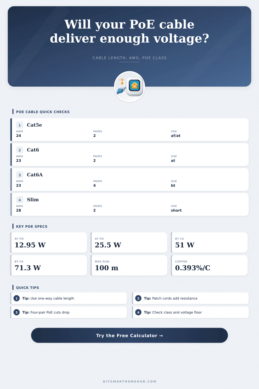
Cat5e cables typically use 24 AWG conductors (thin enough to be bent around corners with ease, yet thick enough to result in noticeable voltage loss across greater lengths). Cat6 and Cat6A cables frequently uses 22 AWG or 23 AWG conductors. That slight increase in diameter make a big difference. Thicker wire means lower resistance. Lower resistance means less voltage loss down the length of the wire. This is why increasing your cable category can address power problems that weren’t an issue previously.
Also note that traditional PoE utilizes two pairs for power. That’s because traditional PoE divides current across two pairs. By contrast, newer standards such as 802.3bt can draws on all four pairs in the cable. This provides twice the conductive area (twice the surface area) for power transmission. This reduces the resistance by half and greatly lowers the voltage drop.
Also keep in mind the effect of heat on copper. As it gets warmer, copper has higher resistance. Your cable could be running at temperatures above room temp which means higher-than-normal resistance when crammed into an attic or wall cavity during the hot summer months. The calculator takes this into account so you can see how well it will perform in real-world situations with less-than-perfect conditions.
Looking at the reference table on the page, you can see which power level each class of IEEE supports. In practice though, things is typically less clean than the standard stipulates. Maybe your device is just really inefficient inside; maybe it draws slightly higher power when you’re using it to maximum capacity. I’ve seen many folks believe their rated wattage is a strict ceiling, forgetting about the overhead needed to actualy get that much power over the wire.
Another area that can cause problems is connector resistance. Patch cords have very slight amounts of resistance along their entire length, as do the ports in patch panels and keystone jacks. Taken individually, this isn’t much. But taken together. Especially if you’ve got a sloppy install with loose crimps and/or oxidized contacts… That added resistance might be just enough to reduce the voltage so the device no longer operates at its intended levels. It is a small thing but it makes a big difference in performance.
When installing a new system, the first thing you should of inspect when designing your network is your longest cables. These should be as thick and short as possible to power high-power equipment. If you have a problem install, ask yourself: what’s coming out of your switches? Is it close enough to what the device requires? If not, you’re running on fumes with nothing left to spare. A little extra heat or some connector degradation might just push you over the edge.
Power over Ethernet is something of a balancing act: High-power devices need shorter wire lengths, which need to be more robust to avoid voltage drop. Ultimately, there’s no way around physics; just play within its boundaries. Use thicker cable wherever possible. Keep your runs as short as practical. Double-check that your switch ports provides enough voltage. A few minutes’ planning up front will save you time troubleshooting the reboot loop. The trick is making sure it stays up when under the greatest load.