LED Strip Resistor Calculator
Calculate series resistor ohms, practical resistor wattage, branch current, voltage margin, and temperature derating for custom LED strip segments and repeated parallel branches.
Calculation breakdown
| Check | Calculated Value | Limit Or Target | Margin | Status |
|---|---|---|---|---|
| Current | 18 mA | 20 mA target | -2 mA | OK |
| LED Type | Typical Vf At 20 mA | Common Segment Count | Resistor Design Note |
|---|---|---|---|
| Red standard LED | 1.8-2.2 V | 3 to 6 in series | Lower Vf leaves more voltage on the resistor, increasing heat. |
| Amber or yellow LED | 2.0-2.3 V | 3 to 6 in series | Use measured Vf for mixed decorative strips. |
| Green or blue LED | 2.8-3.4 V | 3 on 12 V, 6 on 24 V | Cold temperature can raise Vf and reduce current. |
| White LED | 2.9-3.3 V | 3 on 12 V, 6 on 24 V | Warm white and cool white bins may differ slightly. |
| High efficiency indicator LED | 1.8-3.2 V | 1 to 3 in series | Often looks bright below 10 mA, reducing resistor heat. |
| Nominal Resistor Rating | Suggested Continuous Load | Typical Package | Use Case |
|---|---|---|---|
| 0.125 W | 0.05-0.08 W | 0805 SMD or small axial | Indicator LEDs and low-current test strips. |
| 0.25 W | 0.10-0.15 W | 1206 SMD or common axial | Most 12 V decorative LED strip segments. |
| 0.5 W | 0.20-0.30 W | Larger SMD or metal film axial | Higher current branches or warm enclosures. |
| 1 W | 0.40-0.60 W | Power resistor body | Multiple branch prototypes and 24 V drop-heavy designs. |
| 2 W and above | 0.80 W plus | Wirewound or power film | Only when heat has room to escape from the channel. |
| Topology | Resistor Placement | Current Rule | Watchpoint |
|---|---|---|---|
| Single series segment | One resistor in series with the LED string | Same current through every LED and resistor | Supply must exceed total LED Vf by useful margin. |
| Analog strip cut segment | One resistor per repeated strip branch | Total current equals branch current times segment count | Voltage drop along long copper traces changes brightness. |
| RGB shared-anode channel | Separate resistor path for each color channel | Calculate red, green, and blue channels independently | Red Vf is lower, so its resistor often dissipates more heat. |
| Matrix row branch | Each active branch still needs current limiting | Peak current uses resistor value, average heat uses duty cycle | Peak LED current must stay below pulse rating. |
| Indicator rail | One resistor per indicator or small group | Use lower current when brightness allows | Wide tolerance resistors can visibly shift brightness. |
When you succeed, there’s usually a nice little sound of a soldering iron clicking into place. When you guess wrong on that resistor, weeks later there’s likely to be a dead LED. Rarely is it bad wiring, it’s typically one small component that was sized wrong. Grab some generic resistors, throw them in with your LEDs and hope for the best. When it’s in the demo box, all is well. Leave it on overnight or go the full length, and heat will kill the light.
When you know what your desired current is, and what voltage your supplies run at, all you need to do is enter that into the calculator and let it handle the math for you. You won’t have to worry about conversions or coefficients. It is cool that you can click a button and get an answer without having to guess. You should also be able to understand what the numbers represent.
How to Choose Resistors for LEDs
LED isn’t a bulb. A filament bulb is naturaly resistant to current because it gets hot. An LED doesn’t care. If you don’t restrict it somehow (with a passive device such as a resistor) it will pull as much current as possible right before exploding. That device is your power supplys shock absorber.
The other thermal reality of this system is what most people gloss over. Sure, you can get away with just using a regular quarter-watt resistor on some little project, right? Wrong, if that resistor is hidden behind a plastic diffuser or sealed in an aluminum channel. Where’s all that heat going to go in such confined quarters? You can set the calculator to take the heat derating factor into account, reducing the amount you’re allowed to pull from whatever component you have. This allows for that safety buffer, since you may be working in an environment where things runs hotter, and/or airflow is impeded. Even if a resistor is rated for 0.25 watts, it shouldn’t likely be pulling more than half that if it’s caged up somewhere. Small thing, yeah, but when you’re trying to make sure stuff doesn’t fail prematurely, it matters.
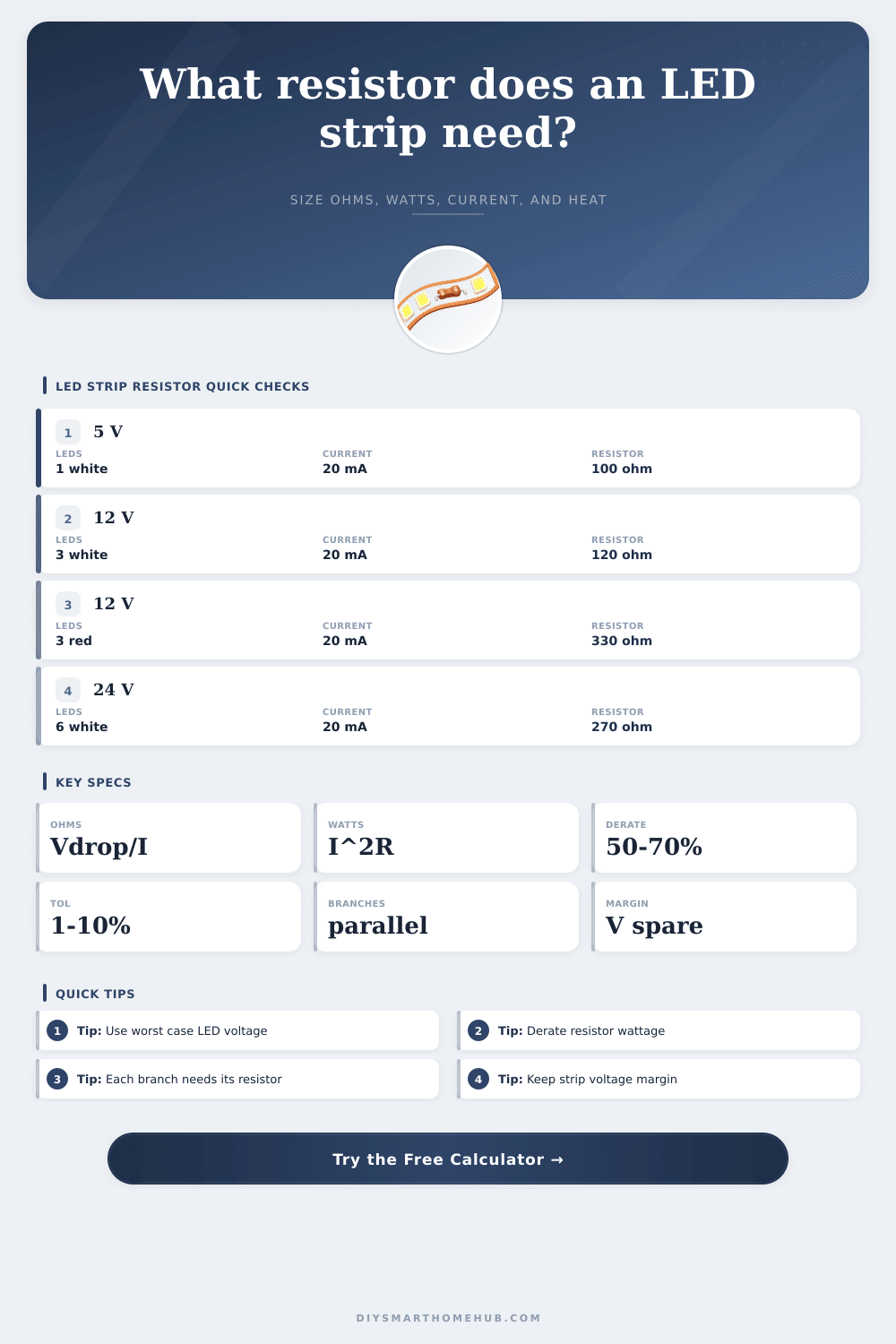
There’s also the matter of the forward voltage trap. In order for an LED to produce light, it needs to reach a certain voltage. Each color has its own requirement. Blue and white LEDs requires roughly three volts apiece. Red LEDs get by on two. So if you stack up a set of three white LEDs, they will require almost nine volts to illuminate. Put that string across your 12-volt supply and you’re left with three volts for the resistor to drop. Plenty of headroom there. Repeat that exercise with red LEDs. A string of three reds requires only six volts to illuminate. That means you’ve got six volts for the resistor to burn off into heat. It uses the same amount of current but doubles the workload, so it dims quicker while getting hot under the collar.
Things get more complicated from there: There is also parallel branches. Without separate current limiters, you can’t daisy-chain these strings. Every parallel path should has its own resistor. Sharing a single resistor across multiple strand will cause the most efficient (or least resistive) strand to hog all the power, starving other strands. The end result is an uneven, dimly lit strip that looks terrible and won’t last long at all. To account for this, the tool lets you specify how many segments should run in parallel so it can sum up their total load on your power supply. Before you solder the last joint, make sure your adapter can handle the total draw.
And then there’s tolerance. Resistors aren’t all equally accurate to the marked value if they’re cheap ones. Ten percent tolerance means you might have 90 or 110 ohms for the same label as 100. That makes your LED’s run hotter if it’s on the low side of that. Tighter tolerance reduces this variation and keeps brightness consistent over long runs. They cost more at first, but you would of spent many fewer hours troubleshooting later.
It’s not simply hooking up some wires, more like tuning an engine. You must weigh total power consumption and thermal considerations against desired voltage headroom. The page shows this in a table where you can sanity-check your instincts, then use it as a reference when designing something new. If you get the voltage/current/power ratio correct, you’ll have LEDs that never shift colors or dim over time for years. If you don’t, well, you’re basically making a slow fuse. Be conservative with your estimates at first. Then check your margin and let the parts do their job in the background.